


ESD Protection Basics with TVS Diodes

At a Glance
Learn about ESD protection basics with TVS diodes, why we need them, and what key parameters make up a typical TVS diode.


Project Overview
In this article, we will be covering the basics of ESD protection and TVS diodes. We will cover a few different aspects, such as why we require ESD protection, how an ideal TVS diode operates, and typical TVS diode parameters.
ESD Protection Basics
ESD, which is short for electrostatic discharge, is a sudden release of electricity from one charged object to another when these objects come into contact. One of the most common ESD examples is when a person walks over a carpet, charges themselves up with static electricity, and then touches an electrical conductor, and releases charged energy in the form of an ESD strike. These ESD strikes can reach voltages of several kilovolts and can be very harmful to electronics—integrated circuits in particular.
Integrated circuits are typically very sensitive to electrostatic discharge as ESD protection is not usually included or if only to a small extent. This is because protections take up quite a lot of silicon real-estate. Therefore, we often need to add external ESD protection.
ICs are typically interfaced with the outside world via connectors, and we need to place ESD protection as close as possible to the connectors.
TVS Diodes
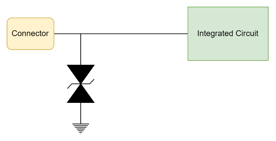
One of the most common ways of protecting against ESD strikes and surges is via the use of TVS diodes. To be protected, TVS diodes are placed predominantly on signal lines, from a connector to an IC. The other side of the diode is typically connected to ground.
In an ideal case, during normal operation and signaling, the diode will simply appear as an open circuit. It will be invisible to the connector, and invisible to the integrated circuit.
Let's assume a person who has been shuffling over a carpet touches a connector and causes an ESD strike. An ideal TVS diode will now appear as a short, and thus shunt all ESD energy directly to ground. In this way, we are preventing energy from reaching the integrated circuit.
When choosing TVS diodes we need to be aware of several main parameters.
Directionality
There are two main types of TVS diodes: unidirectional and bidirectional. In short, the unidirectional TVS diode has an asymmetrical I-V curve, and more importantly, is best suited for protecting signal lines that are always above or below the reference. One side of this diode will usually be connected to ground, and the other side to the signal line. Depending on the polarity of this diode, we either have positive or negative valued signals with respect to ground.
We could also use a bi-directional TVS diode, which has a symmetrical I-V curve, and is best suited for protecting signal lines that can swing above or below the reference.
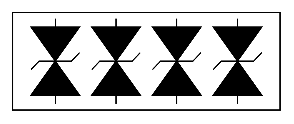
Number of Channels
The number of channels simply states how many TVS diodes are contained in a single package. The reason for having multiple channels is that some manufactured TVS diodes will be packaged for various interfaces. For example, you might get an array of high-speed TVS diodes specifically for HDMI.
Working Voltage
Working voltage is one of the most important parameters to choose for proper operation of a TVS diode. It is the recommended operating voltage of the TVS diode. The signal voltage should not exceed the working voltage.
Clamping Voltage
As the name suggests, the clamping voltage is relevant when an ESD strike occurs. While the ESD strike might be at several kilovolts, the TVS diode—at the point when the transient or the surge occurs—will aim to clamp that voltage to whatever the clamping voltage is of that particular diode.
Capacitance
As is the case with any diode, a TVS diode will have some capacitance associated with it. For DC or low-speed signals, any capacitance added to the line is normally not a problem. However, at high-speeds and high data-rates, extra capacitance will negatively impact the signal. Therefore, it is advisable to choose “high-speed” (low-capacitance) TVS diodes for those purposes.
Power Rating
TVS diodes come in various package sizes and power ratings. They will be rated at various peak voltages and current, and need to be chosen appropriately for the required situation.
IEC 61000-4-2 Rating
The IEC 61000-4-2 is a robustness rating of our protection device. What rating is needed is very much dependent on design, on required contact, and air discharge ratings. A higher IEC 61000-4-2 rating gives us a higher level of protection or robustness.
We have examined the operation of an ideal TVS diode, why we need them in our designs, and what key parameters are associated with TVS diodes. Keep in mind that there is plenty more to TVS diodes, TVS diode selection, and TVS diode placement than we can cover in this short article. However, this should be a great starting point for further investigation.
Make sure to add TVS diodes to protect your sensitive integrated circuits and components when you design your next board using Altium!

About Author
Related Resources
Related Technical Documentation
Table of Contents
Design to Release, Without the Friction
- Keep reviews tied to the right version
- Reduce handoff confusion and rework
- Spot sourcing and release risk earlier
- Work solo, share when needed
Get Started
Thank you, you are now subscribed to updates.

