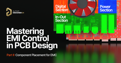


Mastering EMI Control in PCB Design: Decoupling Strategies for PDN


Mastering EMI Control in PCB Design Series
1
2
3
4
5
Decoupling Strategies for PDN
| February 6, 20256
Welcome to the fifth article in our series, Mastering EMI Control in PCB Design. In this article, we’ll dive deeper into power distribution strategies and discuss how to optimize them for better Electromagnetic Interference (EMI) performance in your PCB projects.

Figure 1 - Example of a decoupling strategy in Altium Designer®
A key factor in controlling EMI and improving signal integrity on a digital printed circuit board is implementing effective decoupling strategies. These approaches ensure a clean and stable energy supply for the Integrated Circuits (ICs) on your board.
To achieve this, PCB designers need to create a strong Power Delivery Network (PDN) that meets the energy needs of fast-switching ICs, ensuring they receive the right amount of current from the power supply. Designing a PDN that delivers energy efficiently and on time can be challenging. It requires reducing losses and meeting the impedance needs for high performance.
As data rates and signal speeds continue to increase, designing a PDN with low impedance becomes more important and also more difficult. This is because the impedance profile is closely related to the frequency of the signals being transmitted. Balancing these factors is essential for keeping your PCB designs performing well and minimizing EMI problems. When it comes to designing an effective Power Delivery Network (PDN), several common techniques are used, such as incorporating decoupling capacitors or using power planes and copper polygons in the stackup.
However, some widely accepted methods and myths have proven to be not only ineffective but also detrimental to the performance of the board.
Antiresonance
One popular technique involves using multiple capacitors of different sizes, typically ranging from 10nF to 1µF. The idea is that larger capacitors supply energy to the Integrated Circuits (ICs), while smaller capacitors filter out high-frequency noise. Although this approach seems logical, it can actually backfire when trying to reduce the overall impedance of the PDN. The reason it can be counterproductive is that real capacitors don’t behave ideally; they have parasitic effects that become significant at higher frequencies.
Capacitors exhibit a capacitive impedance only up to their resonant frequency. Beyond this point, the parasitics in the capacitor package begin to affect the impedance, causing the capacitors to behave more inductively. Using capacitors of varying sizes in an attempt to achieve higher overall capacitance and lower impedance can present significant challenges. This is because each capacitor has its own distinct impedance profile, which is influenced by its unique characteristics. Each capacitor also possesses a different resonant frequency, leading to a situation where these impedance profiles overlap with one another. This overlap of impedance profiles results in higher impedance peaks at specific frequencies. These peaks occur due to the interaction between the various resonant frequencies of the capacitors.

Figure 2 - Anti-resonance — Effect of placing different size of capacitors with different impedance profiles in parallel. Source: fresuelectronics.com
As a result, the combined effect of these differing resonant frequencies can create regions of increased impedance, which can negatively impact the overall performance of the PDN and the effectiveness of the decoupling strategy.
To address this issue, it’s better to use Surface-Mount Device (SMD) capacitors of the same type and package, with the lowest possible lead inductance. Placing these capacitors in parallel helps meet the capacitance requirements while minimizing inductance at high frequencies. Additionally, alternating the capacitor leads' polarities can reduce mutual inductance and lower the overall inductance of the PDN.
Capacitor Placement
When it comes to the placement of decoupling capacitors, it's essential to address the issue of inductance, which becomes increasingly significant as signal frequencies rise. To mitigate this, capacitors should be positioned as close as possible to the power pins of Integrated Circuits (ICs) that draw current for their operation. By placing the capacitors near the ICs, we can minimize the distance that the current has to travel, thereby reducing the inductive effects that can hinder performance at high frequencies.
In this context, the designer's primary concern should not be limited to the physical distance the current must travel, but rather, they should carefully consider the exact path the current follows. While reducing the distance between the decoupling capacitor and the pin it is connected to is important, the underlying reason for this is to minimize the parasitic inductance associated with the traces. This close placement helps ensure that the capacitors can effectively supply the necessary charge to the ICs, helping to stabilize the power supply and maintain signal integrity.

Figure 3 - Example of decoupling capacitor placement next to the IC with Altium Designer
By optimizing the path, rather than just focusing on shortening it, the designer can ensure that the current flows in the most efficient manner, reducing the potential for electromagnetic interference (EMI) and improving overall circuit performance.
Therefore, proper path planning can be just as critical as minimizing the distance itself, as both directly affect the parasitic effects that could compromise the stability and functionality of the circuit.
In addition to ensuring the capacitors are placed in close proximity to the integrated circuits (ICs), it is highly recommended to choose capacitors with the lowest possible Equivalent Series Resistance (ESR). The ESR is a critical parameter because it directly affects the efficiency of the capacitor in filtering out high-frequency noise. A lower ESR reduces the overall impedance between the capacitor and the power pins of the ICs, allowing for more effective suppression of voltage fluctuations and noise on the power supply lines. Additionally, capacitors with lower ESR tend to exhibit better performance over a wider frequency range, further contributing to the reduction of electromagnetic interference (EMI) and improving the overall power integrity of the design.
Power Planes
When designing a multilayer printed circuit board (PCB), it is highly advisable to position a pair of power and return reference planes, often referred to as “ground” planes, close to each other within the stackup. Placing these planes in close proximity increases the distributed capacitance between them, which in turn lowers the overall impedance of the power distribution network (PDN).
The ideal configuration involves positioning the signal layers adjacent to the return reference plane, commonly referred to as the “Signal Ground”. This strategic placement allows the return current to flow with minimal loop area, which helps to confine the electromagnetic fields generated by the signals, thereby controlling electromagnetic interference (EMI) and reducing noise. This setup significantly improves signal integrity, as it minimizes crosstalk and electromagnetic coupling between traces, ensuring higher signal quality and reliable communication across the PCB. On the opposite side of the return reference plane, the power plane should be placed. This layout ensures that the power plane can effectively supply energy to the integrated circuits (ICs) without interference from the noise caused by fast-switching signals. By separating the power plane from the signal layers while maintaining close proximity to the return reference plane, you can mitigate noise coupling and create a stable environment for power delivery, ultimately contributing to the efficient operation of the entire circuit. This arrangement enhances both power integrity and signal integrity, making it a fundamental design practice for high-performance multilayer PCBs.

Figure 4 - Example of an optimized 6 layers stackup with Altium Designer®
Using both localized capacitors, placed close to the ICs' power pins, and having power and ground planes close together provides a complete solution. This combination improves the Power Delivery Network, reduces Electromagnetic Interference (EMI), and maintains better signal quality across the board. Additionally, this approach helps to spread power more evenly throughout the PCB and reduces the inductance that would occur if a traditional power routing method were used.
By combining well-placed capacitors with closely spaced power and ground planes, you create a more reliable and efficient power distribution system, ensuring your PCB performs well and stays free of interference.
Looking ahead, our next article will delve into the topic of crosstalk prevention. We’ll explore strategies to minimize interference between signals and ensure cleaner, more reliable communication in your PCB designs, with a particular focus on EMI best practices. You can make sure you don’t miss it by following Altium’s pages and social media, so you can stay updated with valuable insights and practical tips to enhance your designs.
Conclusion
When working on advanced PCB designs, Altium Designer® offers a comprehensive set of tools that can greatly simplify the process for PCB designers and help you create an efficient Power Delivery Network (PDN). One of the key features of Altium Designer® is the Layer Stackup Manager. This tool helps you select the optimal stackup configuration for your PCB based on the specific needs of your system.
Additionally, Altium Designer® includes powerful integrated tools that let you perform detailed simulations of your PDN. These simulations help you analyze and make informed decisions about how to improve your board design effectively.
To elevate your PCB design projects and take advantage of these advanced tools, we encourage you to start your free trial of Altium Designer® and Altium 365™.
This will give you the opportunity to experience firsthand how this complete CAD tool can enhance your design capabilities and lead to more efficient and effective PCB designs.

About Author
Related Resources
Related Technical Documentation
Table of Contents
Design to Release, Without the Friction
- Keep reviews tied to the right version
- Reduce handoff confusion and rework
- Spot sourcing and release risk earlier
- Work solo, share when needed
Get Started
Thank you, you are now subscribed to updates.

