


How Multi-Board Design Tools Can Transform Your Electronics Projects

At a Glance
Multi board PCB design tools give electronics engineers new capabilities and enable unique product designs.


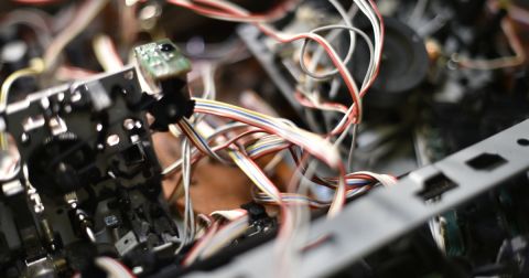
Designing a single circuit board that stands on its own is a very different process from designing a system of circuit boards. Many commercial products don’t operate with just one circuit board; they often use multiple circuit boards that connect with each other in complex ways. These connections can be made with a custom harness, flex printed circuit (FPC) cables, board-to-board connectors, pogo pin connections, or edge connections.
What makes it all possible without creating additional burden in your review process? You need design tools that streamline creation of multi-board assemblies, both logically and physically, on the front end as an integral part of the PCB design process. This means simpler checking for connectivity errors, and the integration of custom interconnect designs within a multi-board system.
What Multi-Board Tools Can Do For Your PCB Design
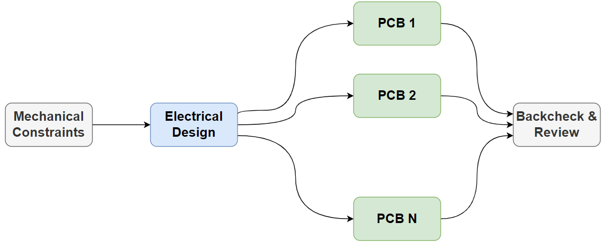
Multi-board design tools enable several important design tasks that can be quite difficult when working on separate PCBs. Multi-board tools focus on integrating the mechanical and electrical aspects of PCB design by aggregating your multiple PCBs into a single project. This means your group of PCBs can be checked mechanically, connected electrically, and prepared for production as a single group.
Without multi-board design tools: Each PCB must be designed individually, and brought back into a complete assembly only after each design is completed and reviewed in isolation. This normally involves the use of STEP models for each PCB, where the PCBs are grouped together into an MCAD application. Crafty designers will know to perform critical placements earlier in the design process and model these as an intermediate step, but it is easy to overlook this portion and later identify a mechanical problem after the electrical design has been completed.
With multi-board design tools: Logical net connections between PCBs in the multi-board assembly can be defined electrically and checked physically. This means it's possible to verify correct board-to-board connections as the assembly is being defined mechanically. Furthermore, it's possible to define mates between objects and the multiport assembly so that they are treated as a single object and can be moved around in sync. This is vital when working in an enclosure object or when importing cable assemblies, harnesses, or FPC ribbons.
Multi-Board Design Workflows
Products with multiple PCBs take teamwork, and this requires a slightly different workflow than would often be implemented when developing products with a single PCB. Because it's a team effort, one PCB designer would be working across disciplines, as well as in parallel with other designers who are designing other PCBs for the multi-board assembly. At some point, everyone comes back together to verify the system will work mechanically and electrically before planning for fabrication and assembly.
To keep each team member on track and prevent design errors, a set of design documentation that is specific to the multi-board assembly is necessary. Some of this documentation is mechanical relating to the arrangement of PCBs, while some of the documentation is electrical relating to the required interconnects between each PCB in the assembly.
Each team may have different documentation requirements, but a good idea is to include the items in the following table in a design documentation package for the multi-board assembly.
|
Pinout drawings |
|
|
Assembly BOM |
|
|
Make it a checklist |
|
|
Mechanical drawing |
|
This level of documentation by your team will eliminate unnecessary repetitions of design reviews while also functioning as a tracking tool for each component in the design. This is just one portion of the documentation needed for a multi-board PCB project; once you start a manufacturing run for the multi-board assembly, additional documentation is necessary to help track progress and maintain a single source of truth for product specifications.
Get Involved With ECAD/MCAD Collaboration
Because multiboard PCB design is so heavily driven by mechanical constraints, teams working on multi-board products need quick access to a mechanical engineer for front-end assembly design and back-checking when the PCBs are completed. This requires a direct integration into MCAD software, whether through the cloud or via an on-premises network. Altium provides just such a link between its multi-board systems design tools and popular MCAD applications for mechanical design. This direct link between the electrical and mechanical worlds is essential for quickly and accurately building multi-board assemblies and preparing them for manufacturing.
Whether you need to build reliable power electronics or advanced digital systems, Altium offers a complete set of PCB design features and world-class CAD tools. To support collaboration in today’s cross-disciplinary environment, innovative companies rely on Altium to easily share design data and accelerate the path to manufacturing.
Interested in exploring multi-board PCB design? Discover how Altium Develop makes it easy to create complex designs and error-free system interconnections.

About Author
Related Resources
Related Technical Documentation
Table of Contents
Design to Release, Without the Friction
- Keep reviews tied to the right version
- Reduce handoff confusion and rework
- Spot sourcing and release risk earlier
- Work solo, share when needed
Get Started
Thank you, you are now subscribed to updates.

