


How the Pros Manage Manufacturing for Multi-Board Projects


The real products you find out in the wild don’t always use a single circuit board. Many products use multiple boards, and this includes everything from your computer to your coffee maker. And whenever you design a product with multiple circuit boards, there are multiple BOMs and multiple libraries to track as the various components get put into manufacturing. For some products, a single BOM can already be a handful, especially when it has thousands of components. What about a project with multiple PCBs and multiple BOMs?
I want to give you some insight into how pro design teams implement a workflow to comprehensively manage their BOMs for multi-board projects. Teams often need to export, scrub, track, and modify data in the BOM as they work to get a product into fabrication and assembly. Software tools can help, but at the end of the day, a process is needed to get a multi-board project over the finish line.
PCB Level or System Level?
Running a project for a single PCB is exactly as it sounds: you have one set of project data, fabrication files, build materials, fab and assembly drawings, and pick-and-place/drill files. Running a project with multiple boards is a different beast as you have multiple BOMs, sets of assembly data, fabrication packages, and not all of these are linked or used at the same time.
As you develop a workflow for product development with multiple PCBs, what tasks are going to be linked with different types of documentation?
|
Fabrication data |
|
|
Pick-and-place data |
|
|
Bill of materials |
|
|
Assembly drawings |
|
Breaking out all these different data types into the PCB level, panel level, and system level makes certain management tasks much easier. In general, it's a good idea to break out each fabrication and assembly packages for each PCB and the entire system, as outlined in the table.
It Starts With Data Tracking
Successfully managing a multi-board manufacturing project requires carefully tracking all of the data for each board as well as the entire assembly. The reasons for this may not be so obvious, but when you look at how fabricators, assemblers, and procurement handle data for multiple boards, they often break it out by separate part numbers.
The best way to keep track of all this data for each sub-component in your multi-board system is to follow these tips:
- Create a consistent part numbering system (and use it!)
- Use your part numbering system in your ERP or PLM system
- Assign one person on the team to track materials orders
- Store and track data for each PCB in a version control system
- As questions come in from fabrication or assembly, track updates in a new revision
BOM Scrub and Parts Ordering
In general, it's always a good idea to do a BOM scrub before sending a design in for production. You never know if one of your desired parts goes out of stock and you need to swap for a different package. For a multi-board project, it's quite common to use a single part number across multiple PCBs. If this is the case, a part going out of stock for one PCB could affect many of the other PCBs in your system.
For this reason, I think it's best to use a combined BOM that is delineated by board for items being scrubbed, created, and kidded. The trick here is that you should delineate the BOM by PCB in your system. Include a column in your BOM that lists the PCB part number for each component.
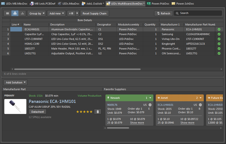
Then, using your distributor's order system or using the BOM Tool in Octopart, upload the combined BOM, and you will be able to see which parts are out of stock or obsolete.

The BOM tool in Octopart is one feature you can use to quickly narrow down to the out-of-stock components or obsolete components in your multi-board assembly.
Once you've compiled alternate or out-of-stock parts into a list and identified alternates, go back into your PCB projects and swap out each part for its alternate. The fastest way to do this in a multi-board project in Altium is to use a .BomDoc file, which will allow you to scroll through and quickly identify and swap parts with alternate part numbers at the project level.
Once a BOM scrub is complete, you're prepared to send off individual part numbers for fabrication and create parts kits for each board. Parts kits are most easily created by breaking out each board into an individual order with a separate BOM. With this process working at the system level first, you won't sacrifice any discounts we're purchasing at Walmart, especially when parts are spread across multiple PCBs.
3D Render Exports
Whether your product will be assembled internally or with a contract assembler, it is always helpful to have a realistic 3D render of the multi-board assembly. In the past, this would require placing STEP files or Parasolid files into SolidWorks or another MCAD application, then manually arranging the individual PCBs and exporting a screenshot.
Altium’s MCAD codesign and the native multi-board assembly tools give you two options for exporting a realistic 3D render of the multi-board assembly.
- If you're a SolidWorks user, pull each of the boards into a SolidWorks project and export a 3D render.
- If you don't have SolidWorks access, you can export a realistic interactive 3D render as a 3D PDF.
In each case, you can also place a 3D body of your enclosure or housing around the multi-board assembly for a more realistic view of your completed product. This includes 3D bodies for cables or harnesses, flex printed circuits, flying leads, or any other mechanical elements like mounting screws or standoffs.
Interested in exploring multi-board PCB design? Discover how Altium Develop makes it easy to create complex designs and error-free system interconnections.

About Author
Related Resources
Related Technical Documentation
Table of Contents
Design to Release, Without the Friction
- Keep reviews tied to the right version
- Reduce handoff confusion and rework
- Spot sourcing and release risk earlier
- Work solo, share when needed
Get Started
Thank you, you are now subscribed to updates.


