


Ensuring Precise Connector Alignment in Multi‑Board Manufacturing

At a Glance
Avoid costly misalignment errors in multi-board designs. Learn how to ensure precise connector fit, electrical integrity, and mechanical alignment from the start.


Connector misalignment in multi-board systems tends to fly under the radar. Until it doesn’t. One subtle offset, one misaligned header, and suddenly you're dealing with bent pins, mechanical strain, or an assembly that just won’t go together. The result? Lost time, added cost, and unnecessary rework tied to poor board alignment or inadequate connector planning.
What makes the difference is catching these issues early and designing with the whole system in mind. Altium makes that possible. With its unified ECAD-MCAD workspace, native 3D multi-board design environment, and electrical rule integration, it gives you the visibility and control to spot problems before they turn into failures.
Let’s break down how to design multi-board systems that align right the first time, using Altium to bridge the gap between what looks good on screen and what actually fits in the real world.
Why Connector Misalignment Compromises Multi-Board Systems
Connector misalignment isn’t just a mechanical issue. It’s a deeper problem that can quietly mess with the overall product quality. Misaligned connectors don’t just cause a one-time assembly issue. They cascade into compromised electrical contact, reduced manufacturing yield, and long-term reliability concerns tied to poor board alignment.
The problem often slips past early design reviews because it hides in plain sight. A connector that looks perfect in the layout view might physically collide with neighboring components, standoffs, or even the chassis once the boards are assembled. What appears acceptable in 2D can lead to bent pins, incomplete mating, or board stress in the physical world. It’s only when you examine the full assembly in three dimensions, in context, that these issues reveal themselves, and by then, a spin or a scrap may already be on the table.
Altium’s Multi‑Board Assembly Workspace for Precise Connector Alignment
In Altium, a multi-board project doesn’t just lump a few boards into a shared 3D space. It treats each individual board as a modular unit within a larger, hierarchical system. Each board is defined in its own PCB project, then brought into the multi-board schematic as a module, where logical connections between them are clearly mapped. This system-level schematic forms the electrical backbone of the entire product.
From there, each module references a specific PCB project and layout, making it possible to drive both logical connectivity and physical integration from a single source of truth. Once the schematic is defined, the multi-board assembly document lets you place and mate the physical boards together in 3D, ensuring alignment board precision and verifying that interconnects align before you ever hit fabrication. And because the flow is fully synchronized, changes in an individual board ripple cleanly across the entire system, keeping your design tightly integrated from concept through production.
Ensuring Board Alignment Through Mechanical Fit and Connectivity
You can’t rely on mechanical alignment alone to keep a multi-board system intact. Electrical and mechanical domains have to move in lockstep.
In Altium, electrical consistency is enforced through multi-board ERC checks, making sure pin functions, net assignments, and interface expectations are matched across boards. But even if the logic is solid, the physical world can still break the system.
Connectors with no keying, unclear orientation, or symmetrical layouts leave too much room for human error. A connector might pass every ERC in your tool, but if it can be plugged in backwards or offset by a row, you’re looking at a real-world failure waiting to happen. That’s why good design isn't just about signal correctness. You also have to make sure the board alignment physically prevents incorrect assembly. When mechanical and electrical constraints reinforce each other, that’s when the system becomes bulletproof.
Engineering the Multi-Board Design Process for Reliable Connector Integration
Rather than rattling off a checklist of rules, let’s walk through what a solid multi-board design flow actually looks like in practice and where Altium fits into that process.
1. Start with a Connector Strategy
It starts with a connector strategy. Don’t leave it until the layout. Choose early whether you're using mezzanine headers, edge cards, flex, or rigid board-to-board links. If a connector can be flipped, rotated, or inserted off-axis, then secure it with keying features or switch to a more robust alignment board solution that eliminates ambiguity.
2. Build the System Logically
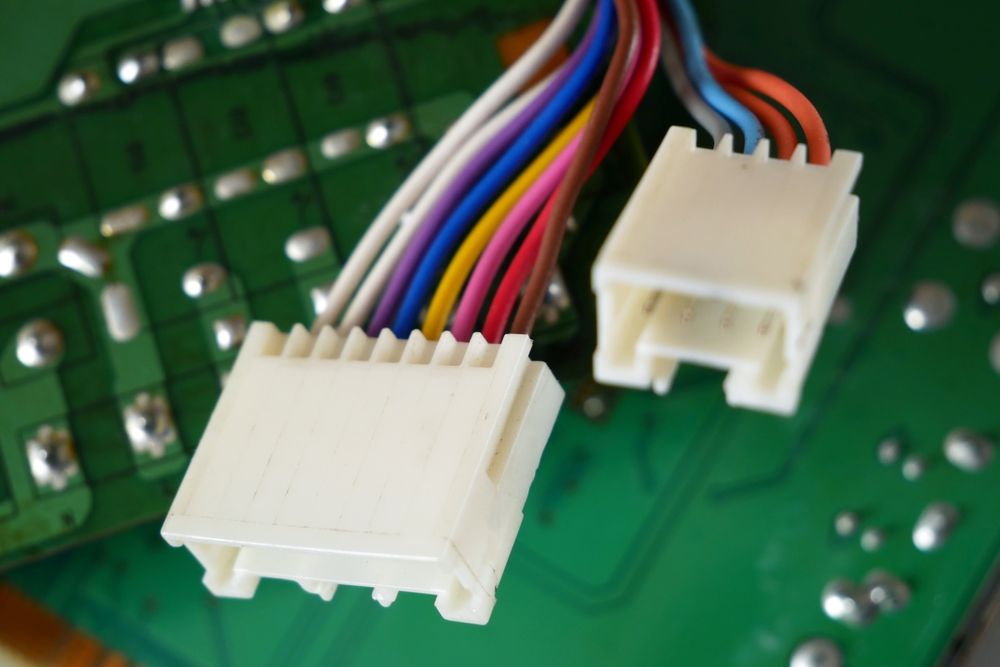
From there, you build out the system logically. Create your .PrjMbd multi-board project, bring in each PCB as a module, and define how they’re connected (whether directly, through cables, or via harnesses). You form the electrical backbone of the system and keep signal intent aligned across the stack.
3. Assemble the Physical Layout
Once the system is defined, shift to physical space by generating an .MbaDoc. That’s your multi-board assembly environment. Here’s where you load up the referenced boards, any enclosure STEP files, and start arranging things the way they’ll be built. Precise connector alignment becomes verifiable, not assumed. Use mating tools to eliminate misalignment and mechanical surprises.
4. Sync with Mechanical Engineers
If you’re working with mechanical engineers, this is also where ECAD and MCAD start to merge. Altium’s mechanical codesign lets you push and pull board placement and mechanical constraints with tools like SolidWorks or Fusion 360, so everyone works off the same model. No exporting back and forth, no outdated STEP files floating around.
5. Check Everything
With everything in place, it’s time to run the checks. That means both logical rule verification and mechanical collision analysis. You want to catch everything – net mismatches, pin misalignments, shroud interference, enclosure clashes. And you want to catch it before you order anything.
6. Iterate Until It’s Right
Finally, iterate. Adjust footprints, revise connector locations, optimize integrity mechanical connectors, or add standoffs and guides until the entire system checks out, electrically and mechanically. Then, and only then, you're ready to build.
Connector Alignment’s Impact on Signal Integrity and Power Distribution
Connector alignment doesn’t stop at mechanical fit. It sets the stage for a chain of dependencies that touch every part of your design. Each connection in multi board design influences power delivery, signal quality, and mechanical reliability. One misplaced via or misalignment connector can create impedance mismatches, timing skew, or jitter—problems that simulations won’t always predict.
That’s why alignment isn't just a mechanical checkpoint; it's a design-critical function. High-speed or high-current applications amplify the risks. Board alignment affects how current flows, how signals propagate, and whether your ground returns stay intact.
In this multidimensional context, you’re doing more than verifying that components fit. You’re confirming that power rails remain consistent across connections, that return paths are preserved through every alignment board interface, and that signal transitions maintain integrity. Ignore any one of these, and the entire system starts to degrade. In multi-board systems, mechanical, electrical, and signal domains are interdependent—and they tend to fail together.
Avoid Connector Misalignment with Rigorous Multi-Board Design
Connector misalignment isn’t some minor oversight. It’s a cross-disciplinary failure that spans mechanical precision, electrical integrity, and process control. It seems harmless until it triggers a board re-spin, delays a production run, or worse, undermines a customer’s confidence.
Altium brings everything you need into one environment to catch these issues early: true 3D mating, real-time collision checks, system-wide ERC, and direct collaboration with MCAD tools. When connector alignment is treated as a core part of system design, not a last-minute fit check, you’re avoiding mistakes and building hardware that fits, functions, and ships exactly as intended.
Interested in exploring multi-board PCB design? Discover how Altium Develop makes it easy to create complex designs and error-free system interconnections.
About Author
Related Resources
Related Technical Documentation
Table of Contents
Design to Release, Without the Friction
- Keep reviews tied to the right version
- Reduce handoff confusion and rework
- Spot sourcing and release risk earlier
- Work solo, share when needed
Get Started
Thank you, you are now subscribed to updates.