


Peak Electrical Performance in Multi-Board Designs With Advanced Simulation and Compliance Tools

At a Glance
Achieve peak performance in multi-board PCB systems with advanced simulation, compliance tools, and seamless ECAD-MCAD collaboration.


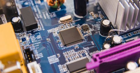
Modern electronic systems increasingly rely on multi-board designs to achieve compact form factors, modularity, and serviceability. But distributing functionality across multiple PCBs brings new complexity. Power integrity, signal quality, electromagnetic compatibility, and mechanical alignment all must be validated at the system level, not just on individual boards.
Altium addresses these challenges through a unified design environment that integrates simulation, multi-board project management, 3D mechanical modeling, and real-time compliance tracking. With the right tools and best practices, engineering teams can create robust, high-performance multi-board systems with confidence.
True Multi-Board System Design, Not Just "Multiple Boards"
Multi-board systems are not simply collections of individual PCBs. They are interdependent subsystems with shared electrical, logical, and mechanical interfaces. Each board must be coordinated with the others as part of a cohesive whole. Altium enables this integration through native multi-board project management (*.PrjMbd), which allows multiple PCB projects to be logically and physically linked within a single environment.
Designers can define and synchronize interconnects across boards, verify mechanical fit using full 3D assemblies, and catch misalignments early. For example, in a design where a main board connects to a power board and a UI module via board-to-board headers, Altium’s multi-board editor ensures connectors align correctly in both schematic and mechanical views, eliminating post-layout surprises.
Built-In Tools for Early Risk Mitigation
Altium integrates layout-aware validation tools that empower engineers to catch critical issues early in the system design process, especially in areas like power delivery, signal integrity, and board-to-board connectivity.
It supports proactive decision-making through:
- Layer stack design and impedance calculators that guide the creation of stackups and trace geometries optimized for controlled impedance routing.
- Real-time DRC and ERC enforcement, ensuring that trace widths, clearances, net assignments, and differential pair spacing meet design rules, particularly at connector interfaces.
- Native 3D collision checks to ensure headers are aligned, enclosure collisions, or inadequate spacing in tight mechanical assemblies.
Together, these features help engineers mitigate layout and integration risks that could otherwise lead to costly redesigns or system failures.
Power Distribution and Connector Integrity
In multi-board systems, power distribution is often spread across connectors and narrow routing channels, each a potential point of failure. IR drop along long traces, undersized power planes, or insufficient return paths can cause voltage instability or even device malfunction.
Altium provides tools to simulate and validate power delivery networks at the system level. For example, when a switching regulator on one PCB supplies power to another board, simulation can show where trace width or connector capacity is insufficient, or where ground return currents may introduce noise. Designers can then reinforce power paths, reallocate pin usage, or add decoupling near the load, all before layout is finalized.
This kind of analysis is critical in systems like industrial controllers or embedded platforms, where power enters through one board but must travel across several modules to reach distributed components.
High-Speed Confidence in Multiboard Systems: SI Analyzer by Keysight
Multiboard designs bring flexibility, but also risk, especially when high-speed signals cross between boards. The Signal Analyzer by Keysight, integrated directly into Altium, gives you a fast, visual way to validate critical nets before they ever leave the board.
Optimized for board-level analysis within multiboard assemblies, it delivers exactly the signal integrity insight you need right where you need it:
- Check impedance, delay, insertion loss, and return loss on key nets
- Catch timing issues in asynchronous circuits before they spread across connectors
- Use heatmaps to spot impedance deviations from your target Z₀
- Generate clean, traceable reports to back your layout decisions
When signal quality matters across interconnected boards, Signal Analyzer helps you catch problems early, without breaking your workflow or needing specialized tools. It’s real-time clarity for complex, performance-critical systems.
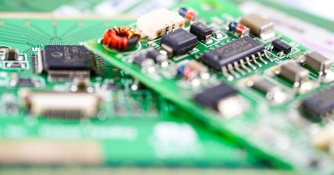
Reducing Connectivity Errors in Multi-Board Systems
One of the most common and costly issues in multiboard systems is miswired connectors or mismatched nets across boards. Altium helps catch these issues early with:
- The Connection Manager, which compares pin-to-pin assignments between boards and highlights mismatches during schematic capture.
- 3D mechanical alignment tools, ensuring connectors align correctly across boards, with sufficient clearance for mating and enclosure fitment.
- No ERC directives and customizable rules, which allow designers to suppress non-critical warnings without ignoring real connectivity errors.
By maintaining schematic-to-layout consistency across boards and enforcing net continuity at the system level, Altium helps reduce silent failures that might otherwise be missed until bring-up.
Collaboration and Lifecycle Support
Multi-board designs demand close coordination between ECAD and MCAD disciplines. Boards must not only function electrically, but also fit precisely within enclosures, align correctly at mounting points, and accommodate thermal or mechanical constraints. Altium’s native 3D environment supports real-time MCAD collaboration, with export/import support for tools like SolidWorks and Fusion 360.
Engineers can co-verify connector fitment, board spacing, mounting hole alignment, and enclosure clearance using shared models. For example, when stacking PCBs vertically in a housing, Altium allows mechanical and electrical teams to confirm connector mating height and tolerance in real time.
Altium extends this integration to supply chain and compliance tracking. It monitors component status, availability, RoHS/REACH compliance, and lifecycle indicators, helping prevent surprises during procurement or certification. For example, if a component on one board becomes obsolete, designers are notified early, before it affects the rest of the system.
Best Practices for Multi-board Peak Performance
To ensure optimal electrical and mechanical performance in multi-board systems:
- Define the full system architecture early, using Altium’s multi-board project framework to manage logical and physical relationships.
- Use simulation tools throughout the design process to validate power, signal, and EMI performance before layout.
- Maintain consistent net naming and connector pinouts across all PCBs to prevent mismatches.
- Validate mechanical fit and connector alignment using Altium’s 3D multi-board modeling tools.
- Design EMI mitigation into the layout from the start, ensuring tight return paths, impedance control, and proper plane continuity.
- Monitor component status, compliance, and sourcing risk to ensure manufacturability and regulatory alignment.
Conclusion
Multi-board system design is inherently complex, but with the right tools and processes, engineers can reduce risk, streamline development, and deliver highly reliable systems. Altium enables this with a unified platform that spans simulation, design, verification, mechanical integration, and supply chain awareness. By adopting a system-level approach from the start, teams can achieve peak electrical performance and accelerate innovation in even the most demanding applications.
Interested in exploring multi-board PCB design? Discover how Altium Develop makes it easy to create complex designs and error-free system interconnections.
About Author
Related Resources
Related Technical Documentation
Table of Contents
- True Multi-Board System Design, Not Just "Multiple Boards"
- Built-In Tools for Early Risk Mitigation
- Power Distribution and Connector Integrity
- High-Speed Confidence in Multiboard Systems: SI Analyzer by Keysight
- Reducing Connectivity Errors in Multi-Board Systems
- Collaboration and Lifecycle Support
- Best Practices for Multi-board Peak Performance
- Conclusion
Design to Release, Without the Friction
- Keep reviews tied to the right version
- Reduce handoff confusion and rework
- Spot sourcing and release risk earlier
- Work solo, share when needed
Get Started
Thank you, you are now subscribed to updates.
