Via-in-Pad in Rigid-Flex Designs: When Space Is Tight, Details Matter
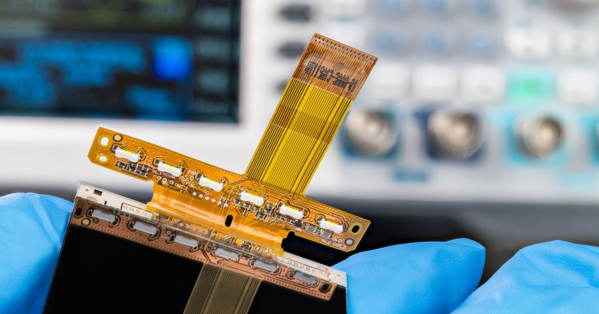
If you've worked on rigid-flex circuit design, you know it’s all about trade-offs. You're combining a number of rigid sections and flexible interconnects, dealing with tight spaces, bend areas, material transitions, and a whole host of mechanical considerations that simply don't arise in standard rigid board design.
And then, somewhere in the midst of a dense component area or a real estate-constrained area, the question comes up: Can I just use a via-in-pad here?
It’s a fair question, and the answer, as with most things in PCB design, is "it depends." Via-in-pad (or VIP) is a powerful tool, especially in high-density layouts. But in rigid-flex, using it without careful planning can lead to problems you’d rather not discover during assembly or, worse, out in the field.
Let's talk about what via-in-pad in a rigid-flex situation really looks like, where it's suitable, what you should know, and how you can set yourself up for success if you decide to go that route.
What Is Via-in-Pad and Why Use It?
Via-in-pad is the practice of placing a plated via directly under a surface mount pad, typically for a BGA or other fine-pitch component, rather than running traces out to a nearby via.
In rigid board designs, it is a proven technique for improving signal integrity, reducing inductive stubs, and accommodating high-density components in close quarters. When space is limited or your BGA pitch is shrinking, via-in-pad can help make the layout feasible.
In rigid-flex designs, you have many of the same space constraints. You're dealing with tight mechanical envelopes and trying to get components close to the edge of a rigid area. So yes, via-in-pad might seem like the perfect solution.
Why Via-in-Pad Becomes Complicated in Rigid-Flex
On the surface, it's easy to consider the rigid sections in a rigid-flex board as another rigid PCB. They're not quite the same, however, especially when fabrication and reliability come into play.
Rigid-flex stackups are thinner than standard rigid boards and consist of different core materials, adhesives, and copper weights. With flex zones, you also have mechanical issues in the Z-axis that you won't find in a stand-alone rigid design.
This has a direct impact on your via-in-pad decision.
You're typically dealing with:
- Thinner rigid cores that affect drill depth and plating control
- Adhesive or bondply layers that can shift or delaminate under thermal or mechanical stress
- Rigid-to-flex transitions that form natural stress points
- Assembly constraints, especially in areas with stiffeners or ZIF connectors
A via-in-pad that would be routine on a standard multilayer board calls for a second consideration in a rigid-flex design.
When Via-in-Pad Is Suitable in Rigid-Flex
That does not imply that you cannot or should not use VIP in rigid-flex. That just implies that you need to be intentional about it.
Here are some cases where it is worth looking into:
- High-density BGA placement in the rigid part of your stackup, where traditional fanout is not feasible due to space or signal integrity constraints
- Shorter paths for sensitive signals that are benefited by having fewer stubs
- Component areas near the edges of boards, where real estate is low and routing escape is challenging
If your VIP is in a stiff region with no direct exposure to mechanical stress or bending, and if the area is well-supported, then it's likely a good and safe choice.
What to Watch Out For
Even when VIP is the right functional choice, there are several design and manufacturing considerations that can make or break your success.
1. Via Fill and Surface Planarity
VIPs need to be filled and planarized to allow component attachment. Non-conductive epoxy fill is the most common method in rigid-flex designs. A copper cap is then put on and then planarized after fill to keep the surface level with the pad.
If this is not performed, solder will wick into the via during assembly and create poor solder joints or voids under the component.
2. Stackup Coordination
Ensure that your fabricator knows which layers the VIP needs to connect to. In rigid-flex, layer interfaces may be flex adhesive or bonding films, which are different from standard prepregs. Drill depth, via aspect ratio, and copper balancing must be considered together. Something that looks great in your layout tool will not necessarily translate to reproducible yields without a perfect stackup.
3. Z-Axis Stress and Reinforcement
Avoid placing VIPs near rigid-to-flex transitions or regions where the board will be subjected to mechanical flexing. Even slight movement over time, such as thermal expansion or vibration, will result in via barrel cracks or pad lifting.
If VIPs must be near a transition, the inclusion of stiffeners or mechanical supports beneath them will reduce movement.
4. Thermal Cycling Effects
Via-in-pad capabilities can concentrate heat during reflow. Thermal mass is usually uneven in thinner rigid-flex designs, and this can compound stress on plated vias and nearby layers. Running a thermal profile and communicating reflow expectations to your manufacturer can avoid issues in assembly.
Collaboration Is Key
One of the most important steps in working with VIP in rigid-flex designs is to talk to your fabricator early. And I mean really early.
Clearly identify VIPs in your design files. Include the full stackup and indicate where the rigid and flex transitions are. If you have mechanical drawings, include them as well. The more complete the picture, the better your fabricator can plan processes like fill, plating, and lamination.
Rigid-flex production already requires tight process control. Adding VIPs just raises the stakes. If VIP is deemed risky or not supported by your fabricator's process, alternatives may be explored:
- Offset (staggered) microvias can be utilized to route out of fine-pitch BGA footprints without placing vias directly under pads.
- Staggered via constructions can offer improved reliability for multiple layers without stress concentrations.
- Via-in-land designs are slightly less dense but reduce stress during assembly and thermal cycling.
Each of these options has tradeoffs, but all are worth considering if VIP doesn't seem like a good fit for your stackup or assembly process.
Final Thoughts
Via-in-pad in rigid-flex designs is an extremely helpful layout technique, but with it comes great responsibility. From stackup planning to via fill and pad design, all the details matter.
The most successful outcomes come from designing ahead. Don't treat VIP as a last-minute escape clause. Instead, work with your fabricator, model mechanical and thermal risks, and add VIPs only where they're suitable and can be properly supported.
With careful planning, VIP will let you get more performance into less space, without reliability compromises. And on rigid-flex, that's very frequently the goal: compact, reliable, and ready for the real world.
Whether you need to build reliable power electronics or advanced digital systems, Altium Develop unites every discipline into one collaborative force. Free from silos. Free from limits. It’s where engineers, designers, and innovators work as one to create without constraints. Experience Altium Develop today!
