Bridging the Gap: When to Use Rigid-Flex Instead of Flex & Connector
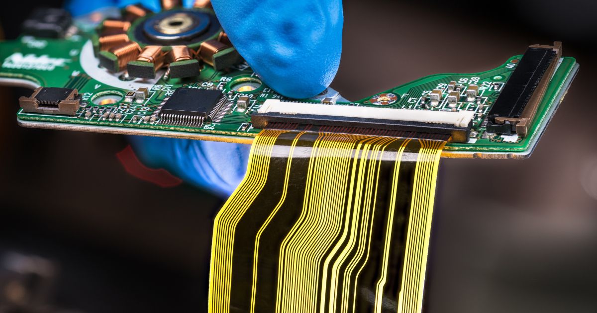
When I talk with designers working on new product development, especially in wearables, aerospace, or compact industrial devices, one topic almost always comes up: "Should we just go with a flex circuit and connectors? Or is this a good candidate for rigid-flex?"
It's a great question, and there's no one-size-fits-all answer. In fact, the answer often depends on how early you start thinking about it. Rigid-flex design requires a bit more planning and a slightly different mindset than what you may be used to with traditional board-to-board connections. But in the right situations, the payoff is huge: better reliability, cleaner packaging, easier assembly, and fewer long-term headaches.
The Traditional Route: Flex Cable & Connector
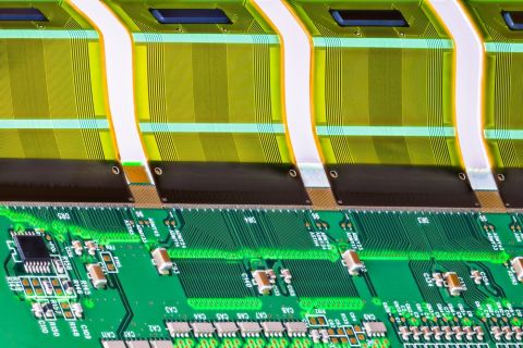
If you've designed electronic assemblies before, you've probably worked with the classic combo: rigid PCBs joined by a flex circuit and connected using board-to-board connectors. This approach is familiar, cost-effective in many cases, and allows for modular design, especially useful in prototypes or early iterations where things may shift.
You also get some benefits on the sourcing and replacement side. If one rigid board in your system changes, you may not need to redesign the whole thing. Just update that one PCB and keep the connector/flex setup as-is.
But there are tradeoffs. That connector? It's adding height, mechanical risk, and potential reliability issues, especially if the device is going into a high-vibration environment, or if it's going to be opened and closed frequently. I've seen more than one project suffer from cracked solder joints or misaligned pins that show up late in testing or, worse, out in the field.
And then there's the assembly process. Aligning connectors during final assembly can introduce opportunities for error: reverse polarity, partial engagement, bent pins, etc. In production, small mistakes like these can add up fast.
So while flex & connector is a perfectly valid approach in many cases, it's not without limitations.
Where Rigid-Flex Shines
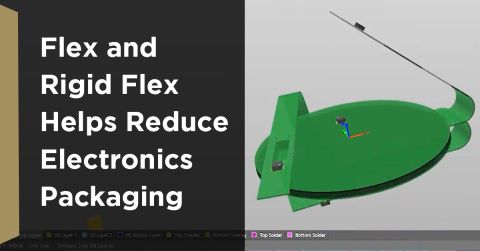
Now let's look at rigid-flex. With this design style, you integrate multiple rigid PCB zones into a single unit, joined by flexible substrate layers. No connectors are needed because the electrical and mechanical connections are built right into the board structure.
It's more complex to fabricate, yes. And yes, the upfront cost is typically higher. But here's where it shines:
Imagine you're working with a device that has very limited Z-height. You're trying to fit everything into a slim housing. So many applications have this constraint, maybe it's a medical wearable, a sensor module, or even part of a drone. Every millimeter counts. A connector might physically fit, but if it forces the enclosure to get thicker or compromises structural integrity, that creates a ripple effect through the whole design.
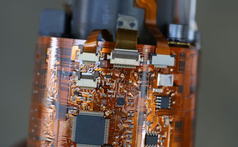
Rigid-flex eliminates that problem. Because the transition between rigid and flex zones is seamless, you can bend and fold the board to fit your enclosure exactly as needed. You're not trying to route around bulky hardware. You're designing the board to follow the product's contours.
That's a big deal. And it's not just about saving space. By removing connectors from the equation, you're removing one of the most common points of failure in an assembly. There's no worrying about long-term contact degradation, no risk of connector misalignment during assembly, and no extra labor required to plug components together. It's a more elegant solution, both electrically and mechanically.
Design for Reliability and Assembly
I've worked with teams that made the switch to rigid-flex not for space savings, but for assembly reliability. In one case, a customer had multiple technicians struggling to align a flex cable into an ultra-compact housing. Assembly time was long, failure rate was high, and rework was tedious.
Once they moved to a rigid-flex design, that entire assembly sequence became plug-and-play, literally one part, dropped into the housing, aligned by design. Not only did it improve yields, but it took pressure off the operators on the floor and helped the company hit their volume targets more consistently.
Another benefit? Fewer part numbers. With rigid-flex, you don't need to source separate connectors, cables, crimps, or interconnect hardware. Your BOM shrinks, and so do your chances of part shortages or last-minute sourcing surprises.
When It's Not the Right Fit
To be fair, rigid-flex isn't always the answer. It's overkill for some applications, and the cost does need to be justified.
If your product doesn't have space constraints and isn't especially vibration-prone you might not gain much by going rigid-flex. Likewise, if you anticipate frequent board revisions during development, using separate PCBs and flex cables gives you more flexibility to make changes without committing to a full redesign.
It's also worth considering your fabricator's experience. Rigid-flex requires tight process control and early design feedback. You'll want to work with someone who understands layer transitions, adhesive placement, and flex zone layout. (And I can't say this enough, involve them early.)
How to Know When It's Worth the Investment
Still on the fence? Here are a few questions I often suggest:
- Are you fighting for space, either in height, footprint, or around corners?
- Will the assembly be subject to repeated vibration, motion, or mechanical stress?
- Are connectors causing reliability concerns or assembly errors?
- Would you benefit from simplifying your supply chain and BOM?
- Is consistent, error-free assembly a high priority for your team?
If you're nodding "yes" to most of those, it's time to give rigid-flex serious consideration.
Final Thoughts
Rigid-flex isn't just a fabrication choice, it's a design philosophy. You're building the interconnects right into the structure of the board. It asks for more upfront planning and usually a closer relationship with your fabricator, but the results are often worth it.
And honestly, once you've seen how beautifully a well-designed rigid-flex circuit folds into place, hugging every contour of the housing like it was meant to be there (because it was), it's hard to go back.
