Top 8 Flexible Circuit Advantages

Early in my career, someone told me that flex circuit applications are really only limited by our imagination. I pondered that for a while, and I couldn’t agree more. Most of these “aha” moments happen when we are passing around a bunch of different samples, and a particular shape or level of flexibility sparks a new idea.
One of the favorite parts of my job is the magical moment when I am working with a designer or group of engineers trying to figure out how to solve a packaging issue, and we are passing around a different sample of flex and rigid-flex designs. Often, at some point, after seeing a particular flex sample, I can see someone’s eyes light up with the idea that may help solve the issue and the brainstorming begins. It is exciting to be a part of that process!
As exciting as I think the possibilities of designing with flex and rigid-flex are, there are people that prefer not to use flex. I understand the hesitation. There is always a learning curve with new technology; new materials to learn, new design rules, maybe even having to find a new fabricator. It can be intimidating. So, in response to the question above, I thought I would run through some of the top eight benefits of using flex and rigid-flex to solve packaging issues. Maybe these will spark some new ideas or provide an incentive to look further into taking the leap into flexible circuitry.
What Are the Benefits of Flexible Circuits?
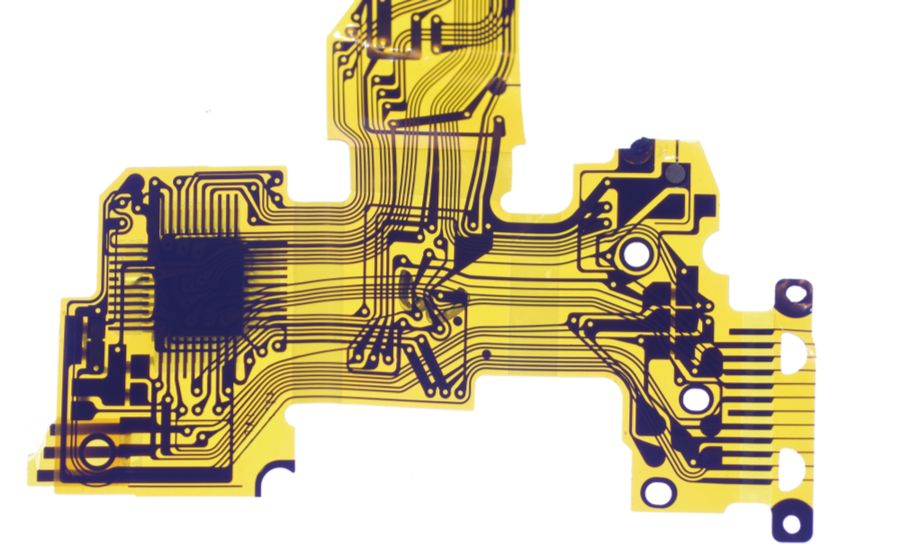
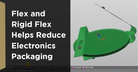
Solves a packaging issue: I think this one is the most obvious. The material can be bent and folded around corners, provide three-axis connection and has no discrete pieces. Electronic components and functional elements can be placed in the optimal position within the product with the flexible circuit able to be bent, folded and formed to make the connections. This is where the imagination is taken to task!
Reducing space and weight needed: SWaP, or space weight and packaging continue to be a hot topic in PCB design. Flexible circuits can eliminate bulky wire and solder connection and depending on components and structure, can save up to 60% in weight and space, significantly reducing package size. Flex materials also provide a lower profile than traditional rigid board solutions.
Reduced assembly costs: Replacing bulky wire and cable reduces or eliminates wiring. This reduces not only the assembly labor costs but the cost of the wire, the cost generating multiple purchase orders, receiving and inspection and kitting. This is worth exploring in more detail.
Facilitates dynamic flexing: Flexible circuits, when properly designed can withstand millions of flexes. Disk drives are a common example with 10’s – 100’s of millions of flex cycles. Another good example are hinges on our laptops. These flexes will withstand 10’s of thousands of flexes over the life of our computers.
Thermal management: Polyimide materials can withstand high heat applications, and thin polyimide dissipates heat much better than thicker, less thermally conductive materials. For this reason, we see significant growth in flexible circuits designs in higher power, higher frequency designs.
Improves product aesthetics: It is a fact that appearance does impact decisions when the user is exposed to the functional element of a product. A favorite example of the power of aesthetics on consumer confidence was when a hand-held cauterizing tool was originally designed and being used in a clinic setting; patients could see the wire that was used for the connection. This was determined to be causing a low rating in patients confidence in the procedure. That wire was redesigned into a very simple polyimide flex circuit, and patient confidence increased significantly. There was no difference in functionality, but the sleek flex circuit scored much higher when surveyed.
Bio-compatibility: Polyimide materials are an excellent choice for bio-compatibility and regularly used for that reason in both medical and wearable applications. Advanced technology can also replace copper conductors with gold conductors giving a fully bio-compatible option.
Increased reliability and decreased opportunity for operator error: Replacing a rigid board and wire cable with a flex or rigid-flex design can significantly simplify the system design by reducing the number and levels of interconnection required. The connections are controlled by a circuit artwork eliminating the possibility of human error.
Wire and cable and rigid boards are a well-known solution and will always be an excellent place to start. It is when the traditional methods just don’t quite solve the design and packaging constraints that you need to start thinking more seriously about flex solutions.
Maybe that is dipping your toe in with a simple flex design and learning the common materials and design tips and tricks to be sure that your flex, does indeed flex as was intended. Or maybe that is jumping in with both feet and tackling a multi-layer, rigid flex with construction with micro vias. Either way, we will be here offering guidance and support.


