


Rigid-Flex Stackups: Where Good Designs Go Wrong Before Layout Even Starts

At a Glance
Optimize rigid-flex stackups with early decisions that prevent failures. Learn how adhesives, transition zones, and plane choices affect reliability.


Are rigid flex design stack up’s more complicated than rigid board stack-ups? Most often they are. Even a simple rigid-flex can be more difficult than a complex HDI design.
Designers who are knowledgeable and experienced in rigid board design, can easily assume the familiar material selection rules still apply. Or at least apply well enough to get through the layout. Sometimes they do and sometimes they don’t. When they don’t, the consequences don’t show up until fabrication or even assembly.
In rigid flex, the stack-up isn’t something that can be refined later. It sets the limits for reliability, yield and cost long before the first trace is placed.
Key Takeaways
- Stack-up drives success so decide early. Rigid‑flex stack-ups are more complex than rigid boards, and the stack defines reliability, yield, and cost before routing begins.
- Choose adhesive vs. adhesiveless intentionally. Adhesive layers add thickness variability and stress. Adhesiveless is often preferred for multilayer/rigid‑flex, tight bends, microvias, and higher thermal exposure at the tradeoff of higher cost/lead time.
- Design the rigid‑to‑flex transition zone. Explicitly define its location/size in fab notes and avoid abrupt layer/copper changes. Failures often appear later (cracking, delamination, copper fatigue), so get fabricator input early.
- Rethink plane layers in flex. Solid planes resist bending and accelerate fatigue. Use cross‑hatching/segmented/partial planes as needed, balancing electrical needs (impedance/returns) with mechanical reliability, ideally via early stack-up reviews with your fabricator.
Adhesive vs. Adhesiveless
Many designers don’t consciously choose between adhesive-based and adhesiveless flex constructions. It often comes from a default stackup, a legacy spec, or whatever was used last time.
On a drawing, both options look similar. In fabrication, they behave very differently.
Adhesive layers introduce variability. They move under heat. They add thickness that isn’t always perfectly uniform and for dynamic flex application, this thickness can be detrimental to the long-term flexibility of the design. None of this impacts fabrication, but it does impact final applications and that fabricators have a smaller margin to work with, especially as layer counts climb or features get smaller.
The following is a common comment during design review from fabricators looking at this:
When we see tight registration, stacked vias, and adhesive-based flex, we already know where the stress is going to show up. We can build it, but sometimes small tweaks in the material stack can have a dramatic impact on yields and reliability.
Adhesiveless constructions are often recommended for multilayer flex and especially for rigid flex constructions. There is better thickness control and equally importantly, more stable Z-axis behavior. That’s why they’re common in designs with microvias, tighter bend requirements, or higher thermal exposure during assembly.
Why don’t all rigid flex designs use adhesiveless material? It is recommended, but the tradeoff is cost and, sometimes, longer lead times.
One approach is not necessarily better. It’s that this decision shapes everything that follows. Once layout starts, changing it becomes unlikely, even when problems begin to surface later.
Transition Zones
Designers tend to think in terms of rigid areas and flex areas. Fabricators, on the other hand, think about the space between them.
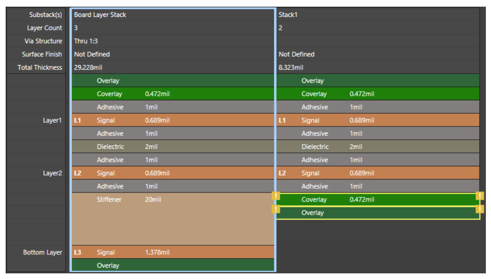
That rigid-to-flex transition zone is typically the area where stress concentrates. It’s also where stackup assumptions collide. Note that in the typical layer stack definition in CAD, there is no explicit definition of a “transition zone” (see below), the location and size of the transition zone must be stated in the fabrication notes.
For example, avoid abrupt layer count changes, plane layers that stop suddenly, copper distributions that look balanced in CAD but behave very differently once laminated. These aren’t unusual. They’re common. And they don’t usually fail in obvious ways.
A fabricator explained it this way:
Most transition-zone issues don’t show up electrically. We see cracking, delamination, or copper fatigue later. By the time it’s visible, the stackup has already done the damage.
That’s what makes this area so tricky. You can’t always catch these problems with a DRC. They often appear during depanelization, assembly, or after the product has been installed and flexed in the field.
Getting advice from your fabricator about transition zone best practices is always recommended. Even when following “industry best practices" it is not uncommon for fabricators to suggest tweaks that help ensure their specific process parameters are successful with your design.
Plane Layers in Flex
Solid planes are known to solve real problems on rigid boards, and designers trust them for good reason. Rigid flex design changes the rules.
Why? Solid copper planes resist bending. Over time, they concentrate stress and accelerate copper fatigue. Even in static applications, they increase stiffness and raise the risk of cracking during handling or assembly.
Cross-hatching, segmented copper, or partial planes can help, but they’re not universal solutions. Each option introduces electrical tradeoffs that need to be considered intentionally, not applied by default.
This is another one of those moments where talking with your fabricator early is important. When designers explain which areas truly need controlled impedance or clean return paths, fabricators can often suggest constructions that protect both electrical performance and mechanical reliability. When that discussion happens late, everyone is forced into compromises.
Why Fabricators Push for Early Stackup Reviews
Across all three of these areas, the same consequence shows up again and again. Once routing begins, options disappear quickly.
A senior process engineer I was working with once told me:
If we review the stackup early, we can usually simplify it, improve yield, and avoid surprises. After layout starts, we’re mostly managing risk.
That comment stuck with me and is something that has been witnessed repeatedly.
Early stackup reviews are where rigid-board habits get challenged and flex-specific considerations come into focus. While it can be an often over-looked first step, it can also be where many rigid-flex designs become simpler, thinner, and more reliable.
Final Thoughts
Rigid-flex designs require different thought processes. Adhesive choices, transition-zone planning, and plane-layer strategy are not secondary considerations. They are foundational.
Designers who involve their fabricator in the conversation early in the design process tend to have fewer surprises when they get to fabrication. A reliable product is always the goal and a smooth design to fabrication to process is a great start.
Whether you need to build reliable power electronics or advanced digital systems, Altium Develop unites every discipline into one collaborative force. Free from silos. Free from limits. It’s where engineers, designers, and innovators work as one to co-create without constraints. Experience Altium Develop today!
Frequently Asked Questions
Why are rigid‑flex PCB stack-ups more complex than standard rigid board stack-ups?
Rigid‑flex stack-ups combine materials with completely different mechanical behaviors, which means the stack-up must account for bending, thermal cycling, adhesive movement, and transition-zone stress. Unlike rigid boards, the stack-up can’t be refined later. Its early definition directly impacts reliability, manufacturability, and long‑term durability.
Should I choose adhesive or adhesiveless materials for rigid‑flex designs?
Adhesiveless materials are generally recommended for multilayer flex, microvias, tighter bend radii, and high‑temperature assembly because they offer better thickness control and more stable Z‑axis behavior. Adhesive-based materials are cheaper but introduce variability, increased thickness, and higher risk of copper fatigue in dynamic flex areas. The choice should be intentional, not based on default stack-ups or legacy specs.
What causes failures in rigid‑to‑flex transition zones?
Most failures occur because transition zones concentrate mechanical and thermal stress. Abrupt layer changes, solid planes that terminate suddenly, or uneven copper distribution can lead to cracking, delamination, and copper fatigue. These issues often don’t show up in DRCs; they tend to appear during assembly, depanelization, or field flexing. Clear fab notes and early fabricator review help prevent these issues.
Why do fabricators recommend minimizing solid copper planes in flex regions?
Solid planes resist bending and create rigid “hinge points” that accelerate copper fatigue over time. This can lead to fractures or long‑term reliability failures. Flex regions often use cross-hatched, segmented, or partial planes instead, balancing electrical performance with mechanical flexibility. Choosing the right strategy requires early discussion with your fabricator to avoid unnecessary compromises later in the design.
About Author
Related Resources
Related Technical Documentation
Table of Contents
Design to Release, Without the Friction
- Keep reviews tied to the right version
- Reduce handoff confusion and rework
- Spot sourcing and release risk earlier
- Work solo, share when needed
Get Started
Thank you, you are now subscribed to updates.