


Using ESD Grounding Techniques to Protect Your PCB from Electrical Damage

At a Glance
ESD grounding needs to be implemented in the PCB layout and in the enclosure to ensure devices can be protected from damage.


Whether you're repairing a computer or you're handling your PCB, no one wants to have their electronic devices ruined by ESD. Think back to the grounding wristband you would use when installing parts in a computer; the connection between your body and a large chunk of metal in the chassis should be your clue as to how you can protect your devices from ESD events. The function of that connection is to provide a low-impedance path to a large charge reservoir for any ESD pulse that passes into your device.
Any conductor that you use to absorb an ESD event functions as a safety ground, and the most important aspect of ESD protection is implementing a grounding strategy in your PCB layout and your enclosure. The enclosure and PCB layout must work together to provide a preferable path for any ESD pulse away from your components, and that means you need to create the PCB layout around your grounding connection and strategy. In this article, I'll outline the important grounding techniques used to ensure your board can withstand an ESD event.

Grounding Methods for ESD Protection
There are a few important methods that can be used to help protect your design against ESD. We typically associate ESD with large dielectric breakdown events that can produce arcing. However, even an ESD event that produces an electric shock, such as discharge from a human finger, could reach kV levels. At these voltages, taking advantage of ground to divert ESD away from your components is the most effective way to ensure protection. This is essentially the strategy that is used in most systems that could experience ESD and be put at risk of damage.
To keep your electronics protected from ESD, there are three important guidelines to follow in your PCB layout:
- Use ground planes
- Use a chassis ground if available
- Use ESD protection components
Use Ground Planes
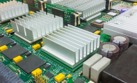
The major function of safety conductors used for ESD protection is to provide a path for the current from ESD to flow so that it does not flow into your components. This is also the function of protection components as described below. A large ground plane in your PCB can provide just such a protection mechanism, particularly when used with ESD protection components. Ground planes are also important more generally; most designs should use ground planes on the layer adjacent to your components as signals, such as in this standard 4-layer stackup.
Some devices will only have a ground plane as their protection mechanism; mobile devices are a great example. However, some devices will have access to an additional safety ground region in the PCBA chassis.
Use a Chassis Ground
This is where the computer tower case grounding strategy should become obvious.
Enclosures can be used as a ground when the have some built-in conductors. These enclosures serve a dual role of providing a mounting point for a board through mounting holes, as well as serving as a safety ground for the system. By "safety ground" we mean that the enclosure can receive an ESD event and withstand the received energy without failing or delivering that energy to the components. The best way to ensure this in systems with a chassis ground is to include two low-impedance connections:
- A direct connection between the chassis ground and earth
- A low-impedance connection between the system ground and chassis
The first case applies when a device is being powered from a utility outlet (could be AC or DC), or in power distribution equipment that can run a connection direct to the earth (e.g., from a utility pole). Read more about this first case here. The second case applies regardless of the presence of an earth connection.
These screws often attach the PCB to a grounded chassis, which is a standard strategy used in consumer telecom and computer equipment to help reduce the severity of ESD events and provide multiple locations where energy in an ESD pulse can be diverted to the chassis ground.
The final important point here is how the chassis ground is integrated into the should not be used to carry signal return currents, it should only be used to shield the system from radiated EMI and ESD from external sources. Some systems like desktop computers will use a chassis ground region as a piece of metal in the enclosure, but the user will not interact with the chassis ground because this ground is concealed from the user by an insulating material (e.g., the plastic casing in the enclosure). In this case, the chassis ground could carry a return current without creating a safety issue for the end user, but in this case a ground plane on the board will often be the lowest-impedance, most direct path to the bridged earth/chassis connection point.
Use PCB Level Shielding
PCB shielding is fabricated from small strips of sheet metal and is typically molded into a shape to surround some of the components on a circuit board. These shields can also be found as off-the-shelf components with specific sizes, making them very useful as a last-minute addition during a board re-spin. They are often placed as SMD components, while physically larger heavy-duty shields can be mounted as through-hole components.
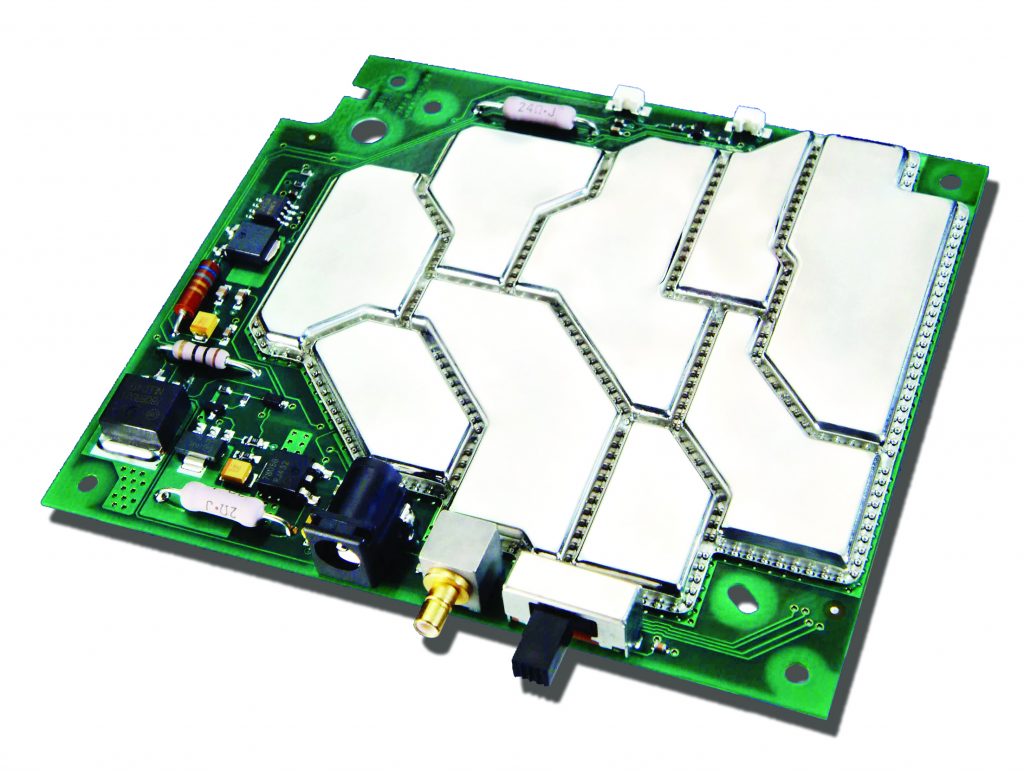
Multiple PCB shielding sections addded as surface-mount components. [Source: XGR Technologies]
These shields play a similar role as a chassis ground in a device where there is no chassis with an earth connection, or they effectively act like a chassis ground in a subassembly within a device. The shield is connected to the ground, and in this way, it can absorb an ESD pulse and direct it away from the protective components. PCB shields also provide another layer of mechanical protection to electronic components. Note, however, that these shields are rarely exposed to the end user and instead are hidden from view in the device enclosure. Still, they are useful in cases of performing rework, handling by technicians/assemblers, or handling by an engineer in general.
Use Shielded Connectors
ESD often occurs at connect pins because these are commonly exposed to the environment and the user of an electronic device. Connector pins that are handled by a user can admit an ESD pulse into the PCB. If ESD protection measures are not located on the impacted circuits (see the next section), there is the possibility that these parts could be damaged.
Shielded connectors include a shroud that surrounds the pins and can function as a sink for ESD pulses. Three common examples of standardized connectors with integrated shielding include:
- HDMI
- USB
- RJ-45 (Ethernet)
- Older computing peripheral connectors
There are many other non-standard connector options which are available off-the-shelf from well-known connector vendors. For example, Samtec, Molex, and Amphenol all supply shielded connectors with high pin counts and/or high voltage/current handling.

The shroud on a connector requires a connection to ground, a topic which has led to many EMC failures and challenges regarding the use of shielded cables. There are three typical ways a shielded connector will be connected to the system ground or chassis ground:
- With a direct connection to the ground net
- Using an RC circuit (typically large R and 0.1-1 nF)
- Using a capacitor (~1 nF)
The exact connection to use depends on the EMC problem to be solved; my preferred way to do this is to do a direct connection, or to place footprints for the RC connection but leave the components DNI (for shielded cables specifically).
Shielded connectors are most effectively used with a grounded ring around the edge of the PCB or with a chassis ground. This allows current from the ESD pulse to dissipate away from the protected circuits. The connection back to the power supply return provides a final connection back to ground where the ESD pulse energy is fully dissipated.
Use ESD Protection Components
Ground is by far the most important part of providing ESD protection, but there is still a possibility for exposed signal lines and pins to receive strong ESD that can damage components. To protect these vulnerable lines, ESD components are used. An example with TVS diodes is outlined in this blog.
There are three broad classes of ESD protection components that are suitable for different protection voltage ranges and response times: TVS diodes (unidirectional and bidirectional), relays (normally open or normally closed), and gas discharge tubes. These three component categories are outlined and summarized in the following table.
|
|
|
|
|
|
|
|
|
|
|
|
|
|
|
|
The response time here is one of the most important specifications. One of the characteristics that makes ESD protection components operate and provide protection is their ability to switch into a conducting state very quickly, which then can divert the current to ground through a low-impedance connection.
During the rising edge of the ESD pulse, there is still a possibility that the pulse damages the component before the protection component can divert the pulse. This is why a faster response time is preferable, as well as lower clamping voltage when available. Another strategy if there is an expectation of strong ESD is to use multiple components in parallel on the vulnerable conductors. For example, gas discharge tubes can be used in parallel with TVS diodes, such as on an RS-485 interface.
With the complete schematic capture and PCB layout tools in Altium Designer®, you can design your ESD grounding strategy and place components to ensure your device will operate reliably in tough conditions. When you’ve finished your design, and you want to release files to your manufacturer, the Altium 365™ platform makes it easy to collaborate and share your projects.
We have only scratched the surface of what’s possible with Altium Designer on Altium 365. Start your free trial of Altium Designer + Altium 365 today.

About Author
Related Resources
Related Technical Documentation
Table of Contents
Design to Release, Without the Friction
- Keep reviews tied to the right version
- Reduce handoff confusion and rework
- Spot sourcing and release risk earlier
- Work solo, share when needed
Get Started
Thank you, you are now subscribed to updates.

