


EMI From Flex PCB Cables in Multiboard Systems


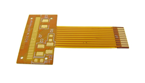
Flex printed circuit cables are very useful for saving space and enabling foldable applications in electronics. Flex printed circuit cables also allow some circuitry to be mounted, and unique fixations to an enclosure are possible by incorporating stiffeners and mounting holes. Although flexible printed circuits may cost more than a standard wired cable option, they can enable higher-value applications which definitely offset the design and manufacturing cost.
Just like any other board-to-board interconnect, flex PCBs can experience EMI problems. This includes radiating EMI from the connectors for signals on the flex interconnect, or the cable from an external source. The unique construction of flex cables admits interesting solutions that should be considered for many designs, including highly rugged military and aerospace systems. In this article, I will run over some of the design factors that address EMI challenges in flexible printed circuit cables.
Usage of Flex Printed Circuit Cables Leading to EMI
Devices that use flex printed circuit cables vary widely in application, ranging from ultra-compact digital devices to highly ruggedized systems for automotive, military, and aerospace. Flex printed circuit cables most often live inside the device enclosure and are not exposed to the outside environment. In some products, such as a modular product, the flex cable is exposed outside the enclosure and will have different EMI immunity characteristics.
Instead of being terminated with gold fingers for a ZIF connector/edge connector, flex printed circuits could be terminated with a standard board-to-board connector, and that connector termination could be a point where EMI, such as an ESD pulse, can enter your system. After realizing these risk factors for EMI, there are some design practices that can be used to suppress or prevent EMI in a flex printed circuit.
Hatched Grounding and Hatch Density
One of the major challenges with flex circuit boards supporting high-speed or high power is that they cannot use solid planes. For flex cables that route power, this often means multiple copper layers that are hatched, as this will allow the flex cable to be formed and bent as needed while still providing the required current-carrying capability. In the case of signal routing, a hatched ground plane is needed to define trace impedance and reduce radiated emissions from signal lines.
If a flex cable is experiencing too much crosstalk or is picking up too much external EMI, tighter hatched grounding may be needed. Shrinking the hatch opening will increase the amount of copper per unit area, and this will increase the shielding capability of the plane layer. Unfortunately, power requirements and channel bandwidth requirements for high-speed signals could get so high that a flex cable will no longer be useful, and a standard wired cable will be needed.
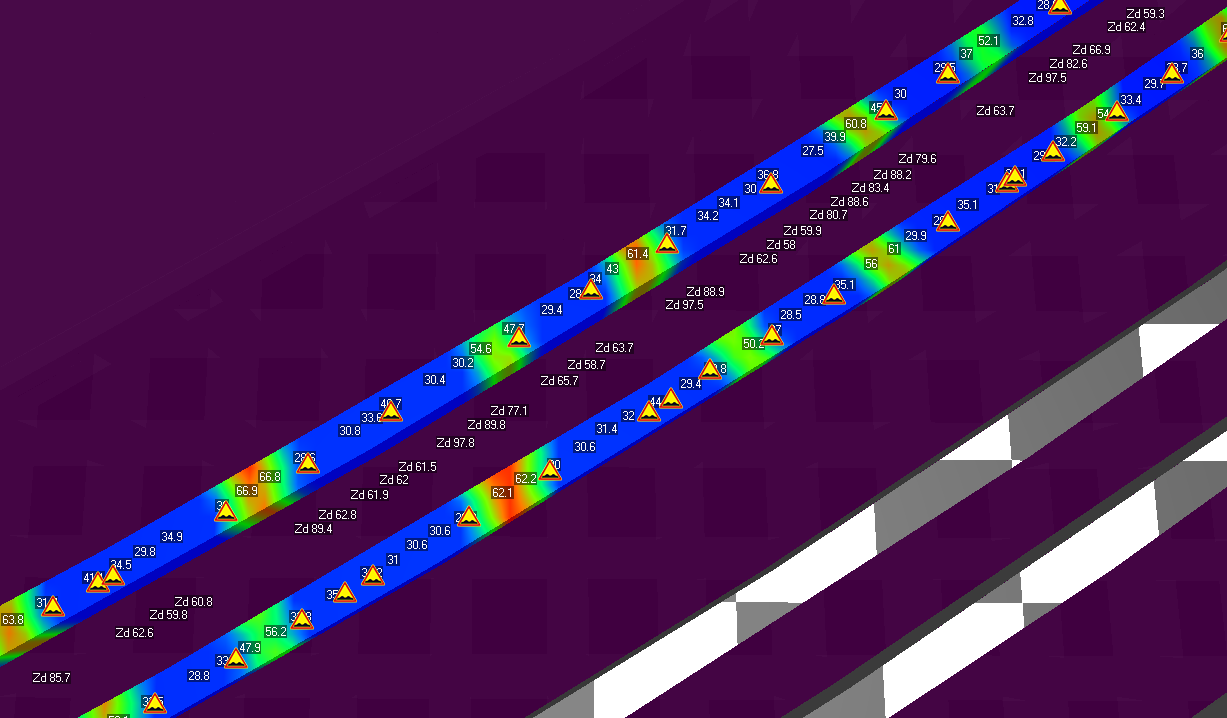
What fill factor of copper versus hatch opening should be used in a hatched plane? It is very difficult to make generalized statements as this depends on how the hatching is used. Hatching can be used as ground for digital signals and to provide impedance control, in which case the hatched ground opening should be smaller than some fraction of the signal's propagation distance during its rise time. In the case of power and ground, the hatch opening should not be so large that it significantly reduces the current-carrying capacity of the flex cable. Simulations are often needed to characterize the impedance, DC resistance, and thermal handling of hatched planes.
A hatched plane impedance simulation shows the periodicity of the hatching, which can allow high frequency EMI to be received by or emitted from the flex PCB cable.
Radiation from Mating Connectors
Signal transitions through mating connectors can be sources of radiated emissions, which can occur in surface-mount connectors, ZIF connectors for plated fingers, and through-hole pin connectors. Flex cables used for high-speed digital interconnects can certainly have problems with radiated emissions from mating connectors, primarily due to lack of sufficient ground in the connector pinout. Flex interconnects carrying power can also be sources of emissions for multiple reasons. Some of the common reasons mating connectors lead to emissions are:
- Impedance mismatch seen by very high-speed signals
- Common mode noise on traces, which radiates from the flex cable
- Insufficient filtering allowing switching noise onto a cable
- Lack of ground in the connector pinout
- Incorrect usage of a cable shield on a shielded connector
- Connecting a connector shield to the system ground rather than chassis ring ground
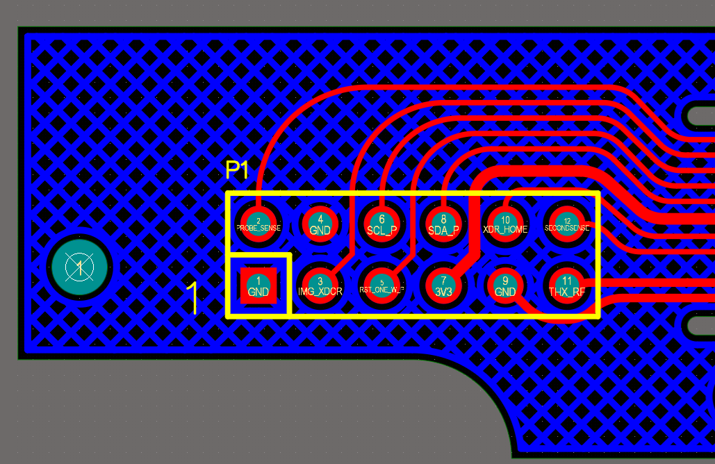
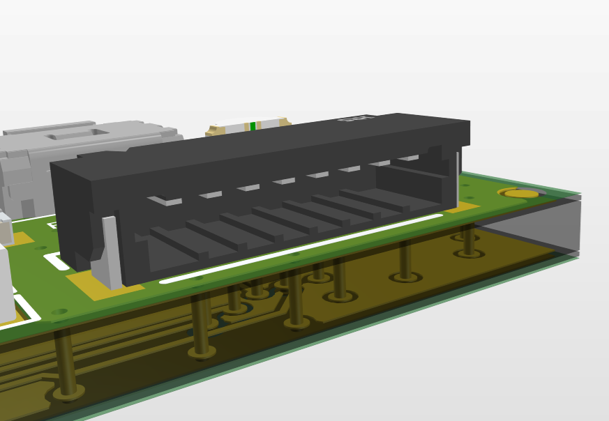
This mating connector for a flex cable can be a source of radiated emissions, typically due to lack of ground or signal reflections.
To help ensure ground reference with good coupling for signals and power is maintained, allocate some pins on the connector to ground on both sides of the mating interface. This will bridge ground across the flex interconnect and will ensure signals are not crossing splits in the reference conductors. As far as shielding on connectors, these are not often exposed to the outside environment, and so a flex cable design may not see any benefit from using shielded connectors inside of an enclosure.
Filtering on Flex Cable Signal and Power Lines
Just as is the case in systems of rigid PCBs and cables, filtering can be used on inputs and outputs to address radiated and conducted EMI. By reducing conducted emissions over a flex cable, radiated EMI can also be reduced once the noise propagates to an insufficiently grounded mating interface. Options for filtering are available, either directly on a flex cable or on a rigid section with a stiffener:
- SMD chokes for common mode noise
- Higher order filter modules
- RC or LC filters built from discrete components
- Ferrites on DC power lines or DC signals
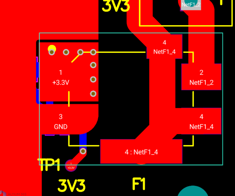
I especially like the filter modules option, especially for power provided at the input or output of a flex cable. These modules can offer higher order filtering with steep roll-off in the kilohertz range, making them very useful for removing noise from DC power. An example of a Murata from an Altium Designer flyback converter project is shown below.
Murata filter module (PN: BNX026H01L) that provides higher order low-pass filtering, primarily for DC power interconnects.
Striplines with Hatched Planes
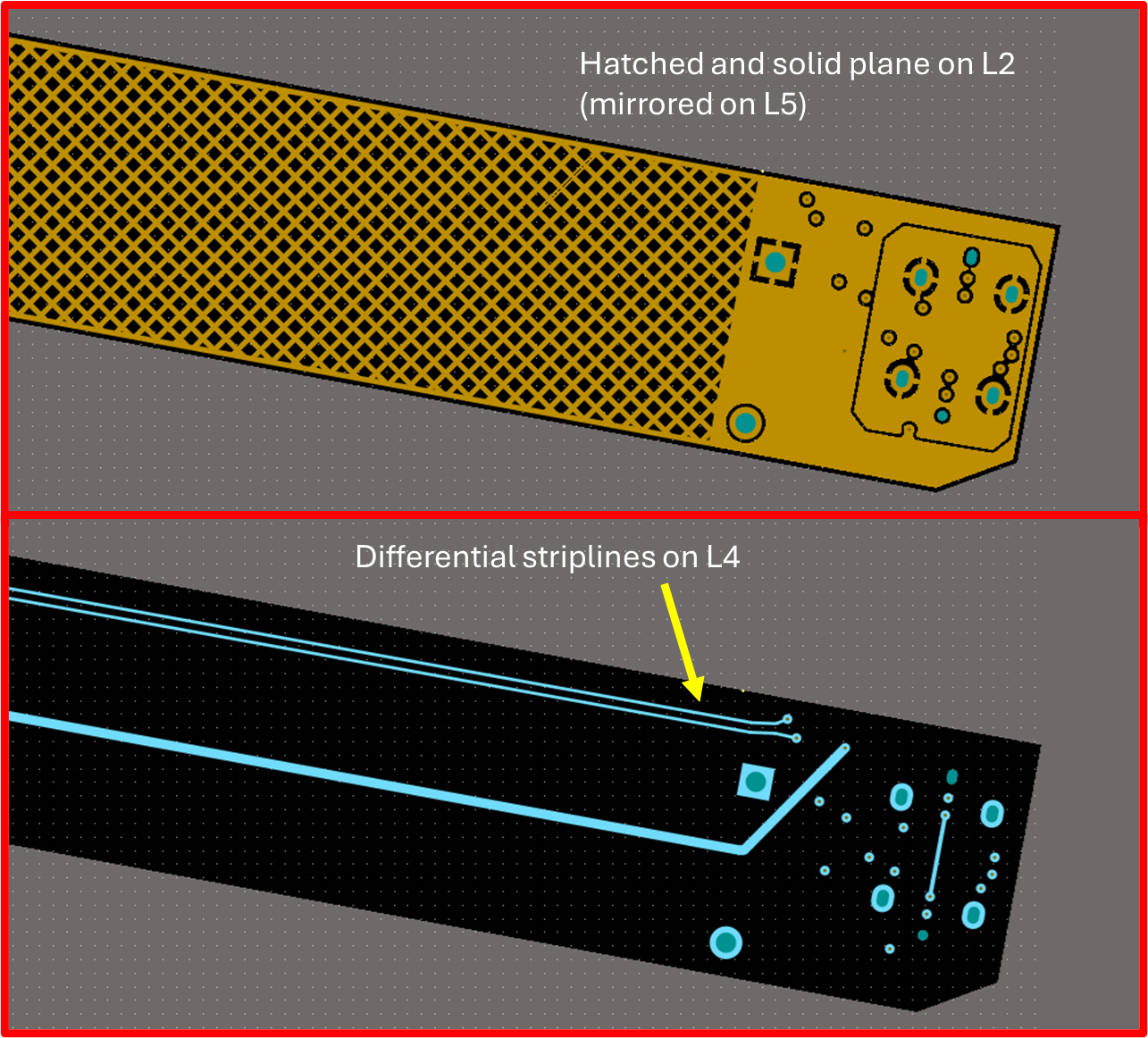
Due to the openings in hatched planes, structures will not have extremely high shielding effectiveness against EMI. When signals are too susceptible or their edge rates are so fast that the hatch plane has trouble containing the electromagnetic field, creating a stripline configuration with hatched planes can be a solution. Place a hatched plane above and below the signal layer to create the stripline structure. The best way to maximize the shielding effectiveness is to offset the hatch structures slightly such that the solid copper in one hatched plane overlaps the hatch openings in the other plane.
At some point, signals with edge rates below one nanosecond become so fast that the hatch structure will fail to maintain signal integrity and will admit too much radiated EMI. At this point, a cable will be the better option. These interconnects tend to be differential, which is helpful to contain noise. Connector vendors offer several options that provide high bandwidth differential signal propagation with impedance matching at connector mating surfaces. Check the data rate specification on the mating connectors to ensure they will support your signal integrity and EMC needs.
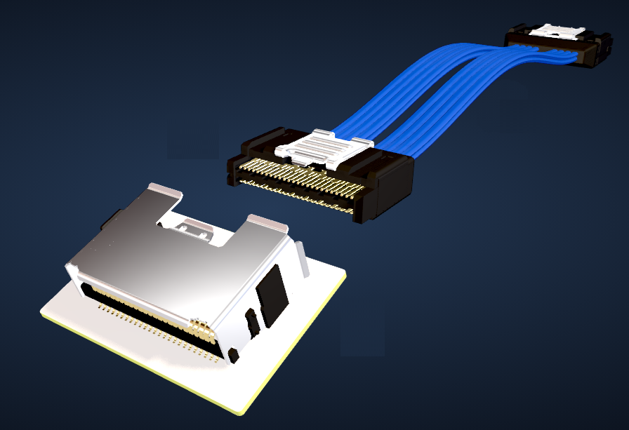
Samtec AcceleRate® high-speed cables are needed once data rates and channel bandwidth requirements become too large.
In closing, flex cables can operate to the same performance as wired cables from an EMI perspective as long as signals are not too fast. This also requires appropriate pinout design to ensure consistent reference conductor connectivity at all mating surfaces and across the flex cable. Filters can also be useful for specific noise sources, DC power, and some signals which may also carry common mode noise.
High-speed single-ended signals with impedance control requirements may not be the best option for use in flex cables. However, differential pairs can be useful thanks to their lower radiated emissions, even when ground is sparse as in the case of a hatched ground plane. In this case, differential pairs may require closer spacing than would typically be used in a rigid PCB, as this will reduce the impedance variations over hatched ground.
Whether you need to build reliable power electronics or advanced digital systems, use the complete set of PCB design features and world-class CAD tools in Altium Designer®. To implement collaboration in today’s cross-disciplinary environment, innovative companies are using the Altium 365™ platform to easily share design data and put projects into manufacturing.
We have only scratched the surface of what’s possible with Altium Designer on Altium 365. Start your free trial of Altium Designer + Altium 365 today.
About Author
Related Resources
Related Technical Documentation
Table of Contents
Design to Release, Without the Friction
- Keep reviews tied to the right version
- Reduce handoff confusion and rework
- Spot sourcing and release risk earlier
- Work solo, share when needed
Get Started
Thank you, you are now subscribed to updates.