How to Use (and Not Use) a Ferrite Bead in Your Design to Reduce EMI

EMI and EMC can be a tricky subjects, and it's often tempting to mis-apply design guidelines to try and reduce EMI. One of these areas relating to EMC in PCB design is the use of ferrite beads. These components are basically filters, and they do perform a useful function on power cords in many electronics. You're probably reading this article on a laptop that uses a ferrite to filter out conducted EMI from the supply line.
A problem begins to arise when you try to apply the same logic to other areas of a PCB. Ferrite beads are sometimes applied for EMI in two ways in attempts to minimize EMI, but the designer ends up creating a new EMI problem if these components are not used correctly. In this article, we'll go over some of the ways ferrites should not be used in a PCB, as well as how they actually operate in terms of their filtering behavior. As we'll see, the same logic that applies to ferrite cores on the input of a bridge rectifier stage in a power system does not apply to the power connection between a regulator and an integrated circuit.
Filtering With Ferrite Beads and Other Inductive Components
Ferrite beads are magnetic components, so it is tempting to think of ferrite beads as inductors that provide low pass filtering functions. They do block high frequencies, but only in a specific band; their impedance tends to maximize and be totally resistive around 100 MHz to 1 GHz. Above that band their inherent capacitance takes over and their impedance begins to drop again. In this way, they aren't the perfect filters. However, these components can be used with other ferrites to address specific types of noise on the input power section. In fact, that’s their most common usage.
Impedance vs. frequency curve for the BLM18PG600SN1D ferrite bead from Murata.
While a bead by itself can’t make a low pass or high pass filter, they can be used for more effective low-pass filtering at lower frequencies (e.g., 60 Hz AC or 120 Hz rectified DC ripple) when combined with shunt capacitors. Then you get what is essentially an LC filter that can provide low-pass filtering functions at sufficiently low frequencies. These are sometimes used on the AC power stage of a system to provide differential-mode noise filtering to ground, i.e., as a Pi filter. In higher power systems, this same circuit design is used with inductor coils as these can generally handle several amps of current. You would then follow this with a common-mode choke and further filtering on the output from your rectifier stage to produce DC power with low ripple.
An example showing these filtering elements an AC input is shown below. Note that L2 is typically a ferritic component (either a ferrite core inductor in high current systems, or a ferrite bead in low current systems).

Why should we worry about current? The reason has to do with saturation. When high DC current is being pulled into the system, the bead can saturate and lose inductance, similar to what happens in a transformer core at high current. In the most basic application, we would have the following set of inductive components involved in filtering noise on the input power stage as shown above:
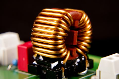
- A ferrite clamp or choke on the input power line (see below)
- A ferrite bead within a voltage regulator to provide some switching noise compensation
- Inductors to provide low-pass filtering of input EMI
- Coupled choke coils specifically targeting common-mode or differential mode noise
Placing these components on the input section of a power stage is much more effective than placing them on the output side. If you do use ferrites for filtering on the output side of a power converter, the acceptable use of these components depends on what you need them to do.
Why Ferrite Beads Should Not Be Used to Prevent Digital Power Rail Ripple
When placed between a power regulator circuit output and the bypass capacitor on input power pins for a digital component, you have basically formed a Pi filter. Therefore, it would be reasonable to expect low-pass behavior at switching converter frequencies. This should not be done with high speed digital components as it will create new noise problems and will not function effectively as a low pass filter.
Why is this the case? There are a few reasons for this. My thought is that the typical recommended uses of ferrite beads are being applied in areas where they are no longer effective, or where they create new problems:
- At DC or low frequencies - At very low frequencies used in switching regulators used to power other low frequency systems, a ferrite bead on the output in a Pi circuit will likely work fine. Common-mode chokes can also be used for common-mode currents in the same way.
- Targeting switching frequencies - This is also an acceptable strategy to specifically target a particular noise source with an inductive component, but only under the conditions in point #1. In effect, the ferrite bead is playing the same role as a low-pass Pi filter or LDO by attempting to pass only the DC portion of the power to the load components in the system.
- For digital components - When used with digital components, the ferrite bead is now presenting high impedance to large current transients with broad bandwidth, which creates strong ripple at the power pins of a digital component. In older TTL components, this was not a problem because they were slower and they could tolerate some level of VCC fluctuation. Today's CMOS components can experience ripple-induced jitter on the output lines due to fluctuations on the power rail.
An implementation for points #1 and #2 is shown below. This implementation is fine in #1 and #2 as it targets conducted EMI while allowing DC to pass. It will not function properly for point #3.

As we can see from points #1 and #2 above, there are some times where a ferrite on the output of a power regulator is acceptable. In fact, the image shown above is the typical way to use a ferrite bead for filtering power supply noise from reaching a static impedance. Using it to suppress noise from affecting a large digital IC as in point #3 is not one of them as you will create a new source of EMI due to ripple on the power rail. This is why we add capacitance to the power rail through the use of decoupling/bypass capacitors as this reduces the PDN impedance at the high frequencies associated with digital signal bandwidths. This will help suppress other noise phenomena in the design, particularly ground bounce.
How Ferrite Beads Impact Power Supply Output Impedance
Ideal power supplies have zero output impedance, meaning they do not experience any power loss and they can respond infinitely fast to transients on the power bus. In reality, power supplies do not function this way; the output response time to a disturbance on the power bus is limited, and they can only respond up to certain speeds (frequencies). This is because power supplies have non-zero output impedance, which can essentially be modeled as a series RL circuit.
Here, we're not only referring to bench supplies, we're also referring to VRM circuits on a PCB that supply voltage to fast digital chips. These components need to supply power at fast edge rates, as described above, but the control loop on the VRM will also attempt to respond to voltage transients on the power rail.
One bad design choice that is sometimes implemented with ferrite beads is to place a ferrite bead Pi filter on the output of a VRM, and then use it to supply power to a digital circuit. An example with TPS546D24S is shown below. There are two reasons this is a bad design decision:
- The ferrite bead will create the problems with resonant behavior as described in the previous section, which can create a strong transient voltage and radiated EMI.
- The ferrite adds to the output impedance at the ferrite bead's resonant frequency, which slows down the control loop response.
This means that, not only are strong transients more likely to occur, but also the power supply circuit will be less able to dampen transients when they do occur.
An example of how not to use a ferrite bead on a power supply. This power supply circuit is intended to provide power for digital components at fast edge rate, and the ferrite bead will slow down the response time of the power supply.
To see some proof of the concepts in action, we can look at a measurement of the output impedance from a power supply circuit versus frequency. The graph below shows a comparison of output impedance measurements for a power supply with and without a ferrite bead used as a filtering element on the output. These data are from Omicron Lab, which they discussed in very great depth in one of their YouTube videos. It should not be a surprise that the power supply with the ferrite bead experiences a wideband impedance peak, which happens to correspond to the ferrite bead's resonant frequency.
Output impedance comparison for a power supply with and without a ferrite bead. Data supplied by Omicron Lab in their webinar Output Impedance of Power Supplies (watch the webinar here).
In addition to impedance measurements, they show a lowering of the noise floor on the power supply output when the ferrite bead is not present in the circuit.
This is why it is best to keep ferrite beads away from the output of your power supply: they slow down the response time of the VRM to fast transients. This means the VRM may be unable to dampen transients which could produce strong radiated EMI, especially when digital components are attempting to draw large bursts of current for I/Os in show timeframes.
To learn more about these points and what many other experts have to say about this topic, watch the video below.
Use Complete Ground Planes Instead of Bridging With Ferrites
One of the primary ways that is sometimes cited as a method to reduce EMI and interference between two sections of ground is to split the plane into two physically disconnected sections, and then bridge them with a ferrite bead. The idea is that the ferrite will provide a return path for any digital or analog signals crossing the gap while also setting the two sections to the same potential, yet it will provide high impedance in one specific frequency range (mid-MHz to GHz).
This is one of the worst EMI suppression guidelines I've ever seen. There are three reasons for this:
- No isolation: Designers will claim that this aids isolation, when in fact it does the complete opposite: it provides a near zero impedance path between two grounds.
- No mid-range frequency return path: At mid-range frequencies, return currents in the isolated side will have no way to return to complete a ciruict; this creates radiated EMI.
- Bad routing: The perception that there is a return path (there isn't) encourages terrible routing practices where a signal will be routed over the gap, thereby creating plenty of radiated EMI.
In mixed signal systems, this always encourages bad routing practices for digital signals and it actually creates a high-impedance return path in a significant portion of the digital bandwidth; this is a perfect recipe for strong radiated emissions. I've been asked to rework boards from other designers that have implemented this strategy and the design ended up failing EMC testing. Once the ferrite is removed and a complete ground plane is used to support routing, then the design ends up passing EMC testing.

To make matters even worse, I've seen designers do this and then add a capacitor in parallel with the ferrite! Now consider what happens when driven right at the ferrite's self-resonant frequency: the above tank circuit now has infinite impedance! Any digital signal with fast edge rate will attempt to pass current via event that includes this tank in its return path experiences the ferrite's high impedance at midrange frequencies, and it will end up radiating strongly. Yet again, another recipe for strong radiated EMI.
Why is this such a bad idea? Here's my summary as to why you should never try to split planes and connect them with a ferrite or a parallel LC circuit:
- Splitting ground planes is usually unnecessary - In mixed signal systems, split ground planes can create more problems than it solves, particularly in systems that use a mix of digital and high frequency analog. In short, it isn't needed except in specialty cases with low frequency analog or when a system requires galvanic isolation. Read more about this here.
- It encourages bad routing - Placing a ferrite bead does eliminate DC offset between the two regions, but it does not function as an effective low-impedance return path between the two sections. Therefore, routing across the gap alongside a ferrite creates a big loop inductance antenna that emits and receives EMI.
- A ferrite alone can still create a high-impedance return path - If a ferrite is used to bridge two ground plane regions, it will still exhibit a high resistance return path even if no cap is present. There is some parasitic fringing capacitance between the two plane regions that will still create a lumped LC resonance with high natural frequency and moderate damping, so a stray pulse received in the inductive loop created by the ferrite could still excite this resonance.
Instead of trying to provide isolation with split planes, practice proper layout and routing practices. This is the best strategy to provide isolation.
General Noise Filtering
AC power connections aren't the place where ferrite beads can be used. Ferrite beads can help filter out low-level noise at low frequencies in many portions of a circuit as long as the desired signal sits within the relevant filtering band for the ferrite and any resonance in the filtering circuit is sufficiently damped. Make sure to check the impedance curve in your ferrite's datasheet and verify that you are using it to target the relevant noise frequency with a high impedance series element. The typical method for using a ferrite as a filter is to pair it with a small resistor in series, or to pair it with capacitors as a T or Pi filter circuit.
Once you have your capacitor and ferrite material in place, you can start filtering out high frequencies. While ferrite beads do have some parasitic resistance that creates damping, LC resonance can still occur. If you really want to use a large capacitor, that risk can be mitigated by adding additional damping with a small amount of series resistance. If resonance does occur, it can lead to a gain of up to 10 dB, so take care to design your filter to avoid resonance if you're working in a bandwidth where this is a risk.
Summary
Now that you know the proper use of ferrite beads to reduce EMI in your circuit, it’s time to design your board. Great PCB design platform like Altium Develop will give you all the tools you need to create your circuits, layout your PCB, and prepare your manufacturing deliverables. When you’ve finished your design, and you want to release files to your manufacturer, Altium Develop makes it easy to collaborate and share your projects.
Whether you need to build reliable power electronics or advanced digital systems, Altium Develop unites every discipline into one collaborative force. Free from silos. Free from limits. It’s where engineers, designers, and innovators work as one to co-create without constraints. Experience Altium Develop today!


