


What PCB Designers Need to Know About Flexible Circuit Materials and Assembly

At a Glance
Learn how smart material choices and early fab collaboration help PCB designers build flexible circuits that perform reliably and assemble without surprises.


Designing flexible circuits can feel a bit like sending your kid off to camp, you pack them up the best you can, hope for the best, and cross your fingers that they come back in one piece. From the PCB fabrication side of things, we see all the ways those good intentions can go sideways, usually because of small choices around materials or assembly that turn into big problems down the line.
There can oftentimes be a gap between what a PCB Designer sees on-screen and what works well in a real-world fab and assembly shop. If we can close that gap, everyone wins: cleaner builds, fewer surprises, and boards that actually do what you designed them to do.
Flex Materials Matter More Than You Think
It all starts with flex PCB materials, and I’m not just talking about what’s technically “flexible.” In most cases, polyimide is your go-to for base material. It’s heat-resistant, mechanically strong, and has the flexibility you need to survive repeated bending. But here’s where things get interesting: how that polyimide is built up and what’s layered with it can totally change how your board behaves and how much it costs.
Take the adhesive situation, for example. You can go with adhesiveless polyimide, which gives you a thinner, more stable build with better high-temp performance. Great, right? But it comes with a higher price tag, so unless your board is going to live in a hot or high-flex environment (like wearables or anything that gets folded and unfolded regularly), you might not need it. On the flip side, adhesive-based constructions are more cost-effective and perfectly suitable for a lot of static applications where the board just bends once and stays put inside a housing.
Then there’s the copper. We see a lot of designs come through where the copper type hasn’t really been considered, but it’s a major factor, especially if your flexible circuit needs to bend often. Rolled annealed (RA) copper is the more ductile option, and it’s much less likely to develop cracks or fractures over time in dynamic flexing situations. Electro-deposited (ED) copper, on the other hand, is stiffer and can be a bit brittle, but it’s cheaper and totally fine for boards that won’t move much after assembly.
What it comes down to is this: the right material choice depends entirely on what the board is actually going to do in the field. Will it move? Will it get hot? Will it be under stress? The more detail you can share with your fabricator about the board’s real-world use, the better we can help guide you toward materials that fit the function and the budget.
Flex PCB Stackups
Now let’s talk about flex PCB stackups, the part of your design that might look perfect in your CAD tool but turns into a heartbreaker in the fab shop.
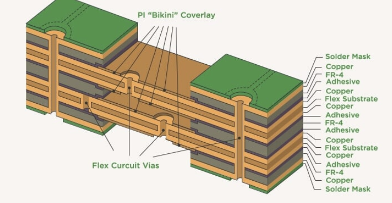
Here’s the thing: flex circuits aren’t just squishy rigid boards. They come with their own set of physics. Every extra layer, every coverlay, every stiffener adds stress to the build. And while it might seem like overengineering adds reliability, it can actually do the opposite. We’ve seen stackups where unnecessary reinforcement or too much copper made the board too stiff to flex properly, or worse, created delamination issues during lamination.
One of the more common issues we see is designers not considering how traces are routed through bend areas. Tight bends with sharp trace angles can cause a lot of issues for fabrication and long term reliability. Rounded corners, gradual curves, and attention to copper thickness can make a huge difference in how well your flex circuit survives the bend.
And here’s a tip: don’t wait until you’ve finalized your design to loop in your fabricator. A quick DFM (design for manufacturability) review early on can help catch little issues before they become expensive production delays.
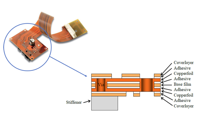
Flex PCB Assembly
So, your flexible PCB is fabbed and looking great. Now it’s time for assembly, which is where we often see a good design start to fall apart, sometimes literally.
The challenge with SMT (surface mount technology) on flex is that the material just doesn’t behave like rigid FR-4. It’s more likely to shift or deform under heat, and that can make component placement or soldering challenging. One of the biggest helps here is adding stiffeners under component areas. Without that extra support, it’s easy for flex boards to warp or bow during reflow, which leads to bad joints and yield issues.
Another area where designers sometimes get tripped up is the ZIF (zero insertion force) connector interface. Those areas have specific thickness and rigidity requirements, and if you leave that out of your documentation, or assume fabricators just “figure it out”—it can delay your project while they clarify specs. Trust me, they would much rather build it right the first time.
Panelization and Yield
Here’s one more thing designers often don’t think about: how fabricators actually handle these boards during fabrication and assembly. Flexible circuits are, well, flexible. That makes it tricky to move, align, and assemble without extra help. If your board isn’t panelized—or is panelized in a way that doesn’t work for the fabrication process, it can slow everything down and increase the risk of scrap.
That’s why it’s so helpful to talk with your fabricator about panelization and depanelization/tooling strategies. Sometimes they will recommend temporary carriers or rails that can be removed after assembly, just to make the process smoother and protect your boards during handling.
So, What Can You Do?
If you take nothing else away from this, remember this: your decisions as a designer don’t stop at layout. The materials you specify, the stackup you create, the thought you put into how the board will be assembled, it all matters. And you don’t have to figure it out alone. Your fabricator should be your partner in this, not just your supplier.
Ask questions. Share context. Let them know if this is going into a smartwatch or a satellite. The more they understand the end goal, the better they can help you get there with fewer delays, better yields, and a whole lot less stress.
Because designing a flexible circuit shouldn’t feel like a gamble. It should feel like teamwork.
About Author
Related Resources
Related Technical Documentation
Table of Contents
Design to Release, Without the Friction
- Keep reviews tied to the right version
- Reduce handoff confusion and rework
- Spot sourcing and release risk earlier
- Work solo, share when needed
Get Started
Thank you, you are now subscribed to updates.