


How High Frequency SMD Passives Work in a PCB Layout

At a Glance
High frequency capacitors, resistors, and inductors are eventually dominated by parasitics. Here's what data sheets can tell you about these components and how to simulate them.


This should come as no shock to anyone familiar with high-speed design: your high-frequency SMD passive components stop functioning as intended once you reach above a certain frequency. Depending on the case size, the reliable operating range for SMD passes tops out somewhere between 10 MHz and 1 GHz. In general, smaller case size capacitors can operate reliably up to higher frequencies due to lower ESR, but this is typically where the analysis of these components ends.
Enter capacitors that are specifically marketed for high-frequency products. High-frequency capacitors are generally tested and qualified at much higher frequencies, in some cases up to 10 GHz or more. These capacitors differ in terms of dielectric material used in the design, their construction, and of course, their internal parasitics when compared to MLCCs. These components target circuits that require discrete passives as an alternative to the large size of printed circuits in these intermediate frequency ranges.
Here, I'll examine high-frequency components, specifically resistors and capacitors that are qualified for operating above 1 GHz. The moral of the story is, if you cannot find manufacturer's test data proving a component is reliable at high frequencies, then it should not be used in such an application.
High-Frequency SMD Passives and Their Operating Limits
Components designed to operate at high frequencies, ranging from 1 GHz to 10 GHz or even higher, are marketed specifically for this purpose. They will have test and evaluation data in the datasheet which shows the operating frequency ranges where the components are expected to work properly. While it is true that some components which are not marketed as high-frequency parts could function as such, these should be qualified in test circuits with S-parameter measurements. Beyond these rated frequency ranges, a high-frequency resistor or capacitor may still deviate from its stated value.
Like any component or circuit that needs to operate at high frequency, parasitic elements cause deviation from the ideal circuit behavior, and high-frequency components have been qualified specifically in the presence of some parasitics. Some typical areas where this might be needed include:
- Impedance matching networks
- Discrete filter circuits
- High-frequency amplifiers
- Power dividers
- Bias tees
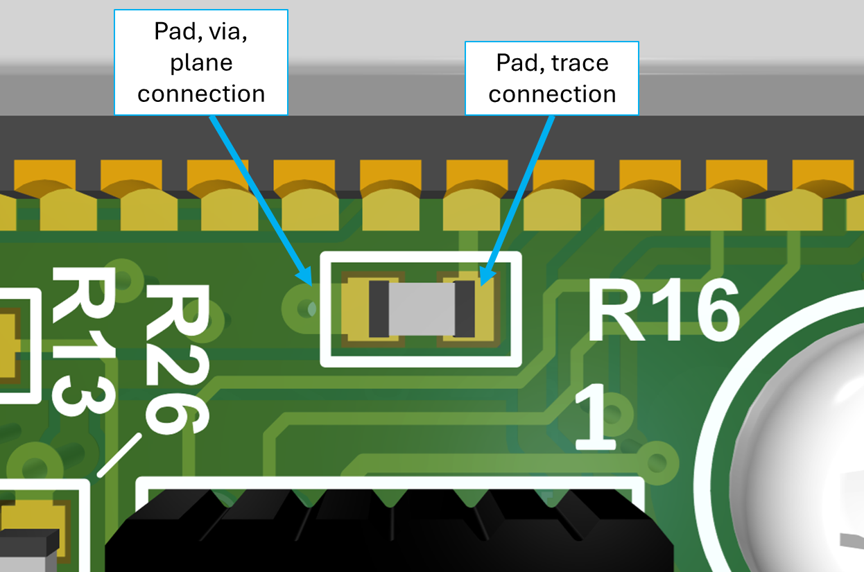
High-frequency components are normally qualified based on specific pad and trace connection arrangements as illustrated in the example below. In the image below, the pads are specifically designed to determine the values of PCB parasitics and packaging in the frequency range of interest.
For this high-frequency resistor, the pads, via, plane connection, and trace will alter the input impedance looking into the component at very high frequencies.
Example: High Frequency Resistor
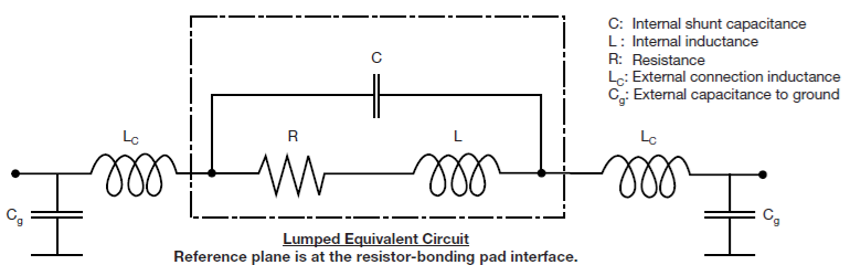
High-frequency components can then be analyzed using an equivalent circuit model, such as that shown below. This circuit model accounts for the nominal behavior of the component, as well as the packaging and PCB parasitics, so that we can better understand what influences the measured performance at high frequencies. In the image below, the circuit model is taken from the datasheet for a high frequency resistor (part number FC0402E50R0BSWS).
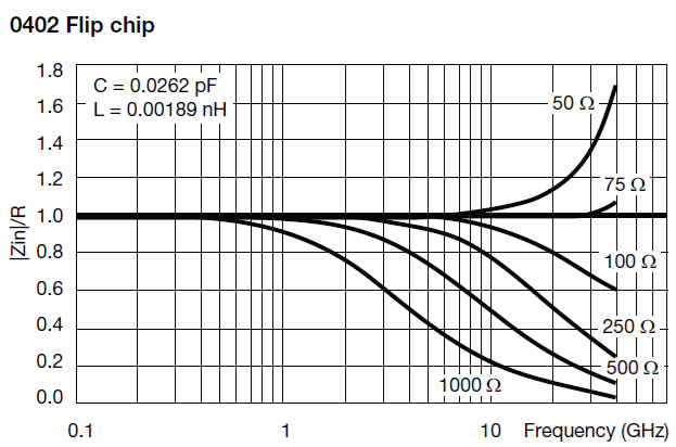
The circuit model can be used to understand and interpret direct measurements of a component's performance as a function of frequency. For instance, look at the resistance graph for the part number mentioned above. This graph shows variation in the measured value from the nominal value as a ratio. At some frequency near 10 GHz, the actual resistance (really the input impedance) of this component can deviate significantly from the nominal resistance for this part number family.
This set of data for a high-frequency component helps you qualify the component's performance within its rated frequency range. This is just one example of the data that would be needed to understand how a component performs at various frequencies. Other components or part number groups may have different ways to display this data, such as with impedance and reactance graphs or with S-parameter data.
Example: High Frequency Capacitor
Capacitors used for high frequency circuits are limited by their self-resonant frequency, just as is the case when capacitors are selected for digital ICs. S-parameter data may be used as the metric for determining whether a certain capacitor is useful in a certain range because, when the capacitor is placed in shunt configuration, the capacitor acts like a low-pass filter until its resonant frequency. Unfortunately, most capacitor datasheets do not show data in this format, even if the part is marketed for high frequency/RF usage.
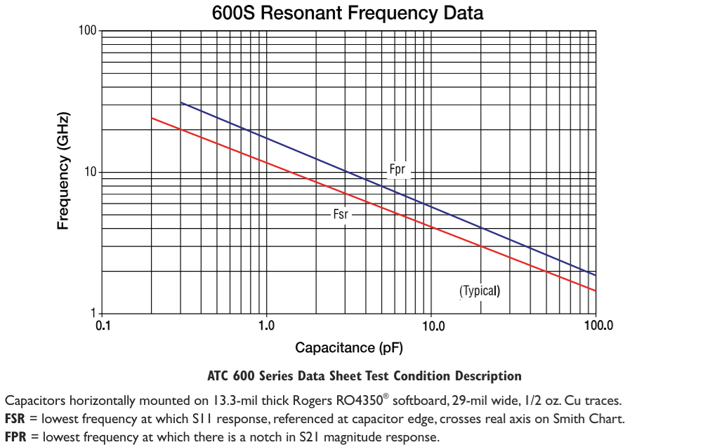
Instead, self-resonant frequency can still be used as the factor determining when a capacitor stops acting like a capacitor and starts instead acting like an inductor. An example of self-resonant frequency data for high-frequency capacitor part number 3456 is shown below. These data can be understood using the standard series RLC circuit model for a real capacitor. You could also convert these data into an insertion loss plot as needed (part number: 600 Series, American Technical Ceramics MLCCs).
How to Use the Above Data
The above examples show two possible ways performance data for high-frequency components can be displayed. How it is used depends on exactly what is being displayed. For example:
-
For a ratio graph, you will know the value of the resistance or impedance directly, so you can immediately see the value of the passive at your target frequency.
-
For an insertion loss, return loss, or self-resonant frequency graph, the impedance can be calculated, but this then requires a second calculation to get the value of the passive at your target frequency.
If you want to use the components in a simulation, it is recommended that you use the circuit model shown above as this will reasonably accurately capture the component's electrical behavior. If you have the S-parameter data, a better option is to extract the S-parameters just for the components, although this may be difficult to derive from a datasheet.
Some component manufacturers provide simulation models for their components so that you can use these in a SPICE simulation for your RF circuit. Of course, you will also need to incorporate models for the transmission lines that connect to a component in order to fully understand the behavior of your RF circuits.
Whether you need to build reliable power electronics or advanced digital systems, use the complete set of PCB design features and world-class CAD tools in Altium Designer®. To implement collaboration in today’s cross-disciplinary environment, innovative companies are using the Altium 365™ platform to easily share design data and put projects into manufacturing.
We have only scratched the surface of what’s possible with Altium Designer on Altium 365. Start your free trial of Altium Designer + Altium 365 today.

About Author
Related Resources
Related Technical Documentation
Table of Contents
Design to Release, Without the Friction
- Keep reviews tied to the right version
- Reduce handoff confusion and rework
- Spot sourcing and release risk earlier
- Work solo, share when needed
Get Started
Thank you, you are now subscribed to updates.

