Low Pass Filter Simulation for Your PCB Design

Many engineers will do some basic calculations by hand in order to understand their filter and amplifier circuits. However, for complex circuits that do not obey standard series and parallel rules, or that use nonlinear components like diodes and transistors, more sophisticated methods are needed. As such, designers need an easy-to-use but powerful simulation application to aid filter design and simulation.
Some programs make simulations difficult, but Altium Designer helps you stay productive by integrating an industry-standard SPICE simulator into your schematic design tools. You can easily create and simulate a low pass filter circuit in this application, or you can incorporate a low pass filter circuit into a larger system. Altium Designer also allows simulation models to be assigned to your components, giving you a complete simulation and circuit design solution in a single application.
ALTIUM DESIGNER®
The only PCB design application with industry-standard simulation features and component management tools in a single program.
Circuit simulations are a fundamental part of electrical engineering, and there is an entire segment of the industry dedicated to creating simulation tools and workflows. Today, nearly anything can be simulated in a PCB layout, but complex circuits often need to be simulated long before a PCB layout is created. Because circuit simulations are so fundamental to PCB design and engineering, designers need easy access to SPICE simulators as they design their circuits.
A low pass filter circuit is one of the fundamental circuits that is used in many larger circuit blocks in a complicated system. In fact, all other fundamental filter circuits can be generated from a low pass filter circuit through a simple transformation of frequency domain data. In order to help designers create and simulate their filter circuits, Altium Designer includes a powerful SPICE simulator in its schematic editor. Designers will have access to much more than a simulator when they use Altium Designer, including component creation and management tools for creating cutting-edge technology.
Anatomy of a Low Pass Filter Circuit
A low pass filter circuit only allows frequencies below a circuit cutoff frequency to be passed into a load circuit. The most basic type of low pass filter circuit is an RC circuit with the capacitor connected across the input terminals of a receiver circuit. In this way, the capacitor shunts high frequencies to ground, while low frequencies down to DC can pass into the receiver. Designers usually work with the transfer function and can visualize the low pass filter characteristics in a Bode plot.
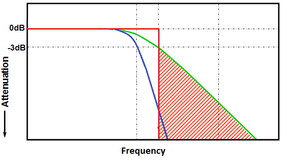
This plot shows the magnitude of the transfer function for a low pass filter. Red curve: ideal response; green curve: 1st order response; blue curve: 2nd order response.
More complex low pass filter circuits can have multiple filtration stages, nonlinear components that provide rectification or capacitance multiplication, or they can be a single stage in a more complex filter. The frequency response of these more complex low pass filters can be difficult to calculate by hand, so circuit design and simulation tools are used to run SPICE simulations of circuit behavior. The best simulation engine will integrate with your schematic design tools to give you an
Other Types of Filter Circuits and Amplifiers
The same components you use to build a low pass filter circuit can also be used to build a high pass, bandpass, bandstop/notch, or multi-band filter. The topology and arrangement of components may be different, but designers can use generic components to experiment with their filter circuits. A single simulation engine can then be used to determine the frequency response of the circuit, as well as the input/output impedance and other signal integrity metrics.
Amplifier circuits are related to filter circuits in that they perform opposite functions. The same tools that are used to design and simulate filters can also be used to design amplifiers. For active filter circuits and active amplifier circuits, designers need accurate simulation models for their components to properly model electrical behavior in a larger circuit. The best set of design tools will give engineers access to all the features and components they need to design and simulate their filter circuits.
- The amplifier or filter circuit you use for simulation will need to be created in a schematic sheet. Altium Designer makes it easy to create a SPICE simulation directly from the circuit diagrams in your schematic sheets.
See some best practices for creating a schematic in Altium Designer.
- Once you’ve created your components and placed them in your circuits, one of the first simulations that is often run is transient analysis.
Learn more about running transient analysis in a circuit simulator.
- Once you’ve created your components and placed them in your circuits, one of the first simulations that are often run is transient analysis.
Learn more about the simulations you can perform in Altium Designer.
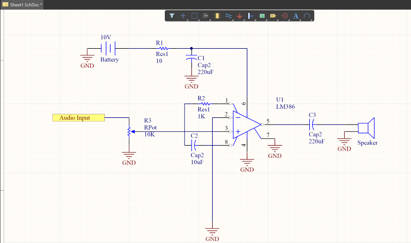
The Schematic Editor in Altium Designer connects users to component libraries and simulation models for creating a variety of circuits, including filters and amplifiers.
Tools for Creating and Simulating Filters and Amplifier Circuits
Filters and amplifiers operate under the same ideas and are basically inverse circuits of each other: filters provide attenuation while amplifiers provide amplification. The design tools used to create these circuits are the same, and designers simply need to create the right component arrangement in their circuit diagrams to create any of the fundamental amplifier or filter circuits. A circuit designer can access components from their component libraries, or they can create components with proprietary electrical models, but these tasks require the right design application.
In addition to a set of circuit design tools, designers need an easy way to access component data and assign simulation models to their components. Simple filter and amplifier circuits may work fine with generic passive components, but real circuits need components with realistic simulation models. The best circuit simulation application will allow designers to create SPICE subcircuits, add simulation models for integrated circuits, and create models for nonlinear components like transistors.
Access Verified Components Through Altium Designer
The power of Altium Designer comes from its unification between circuit design, PCB layout, and data management tools. As part of a complete set of design features, Altium Designer users can access component data for their circuits, including schematic symbols and simulation models. This is done through the Manufacturer Part Search panel, which gives users a complete look at the PCB supply chain. Best of all, Altium Designer’s supply chain features allow a design team to find components with PCB footprints and access updated sourcing data.
- Schematic symbols, PCB footprints, 3D STEP models, and simulation models can be assigned to any component as you create your PCB libraries in Altium Designer.
Learn more about creating schematic symbols for your filter circuits in Altium Designer.
- When you need to create component libraries, Altium Designer makes it easy to assign 3D STEP models to your components.
- Use the Manufacturer Part Search panel in Altium Designer when you need to find component models to use in your circuit simulations.
Learn more about using the Manufacturer Part Search panel in Altium Designer.

The Manufacturer Part Search panel in Altium Designer gives you access to components you can use in your schematics, PCB layout, and circuit simulations.
Store and Manage Your Component and Simulation Data
Once you’ve created your circuits and you’ve prepared simulations, you can generate a significant amount of data from your circuit designs. All of the standard simulations you’ll find in other commercial programs can be found in the schematic editor in Altium Designer. Users can perform the following standard simulation tasks in a user-friendly interface:
- Transient analysis
- Frequency sweeps and transfer function calculation
- Parameter sweeps, such as component values
- Fourier analysis from time-domain data
- Noise analysis
- DC sweeps
- Pole-zero analysis
Doing these simulations with any circuit takes a complete set of component data access and management features alongside powerful simulation tools. You don’t have to make every component for your filter circuits on your own, you can use the Altium 365 platform to access component models within Altium Designer.
Complete Design Management in Altium Designer and Altium 365
Altium Designer and Altium 365 create a complete PCB design ecosystem for creating circuits, building high-quality circuit board layouts, and managing design data. Everything required to design and layout a new circuit board is included in Altium Designer and project data can be easily shared and managed through the Altium 365 platform. No other design platform provides these features in a single powerful application.
- The complete set of CAD tools in Altium Designer helps a design and engineering team move through the entire project cycle. Designers can create schematics, PCB layouts, and manufacturing documentation in Altium Designer’s unified environment.
Learn more about the unified design environment in Altium Designer.
- The schematic editor in Altium Designer is your place to design and simulate filter circuits, amplifiers, regulators, and any other circuit you can imagine.
Learn more about building and running simulations in Altium Designer.
- Altium Designer users have access to component models through the Altium 365 platform. Users can also share and manage their design data through the Altium 365 platform, both within Altium Designer or in a web browser.

You can share all your Altium Designer libraries and projects with the Altium 365 platform.
The days of using separate programs for circuit design and analysis are over. Take control of your low pass filter circuit designs, simulation models, and component data in Altium Designer and Altium 365. No other design application provides this type of connected, collaborative PCB design experience.
Altium Designer on Altium 365 delivers unprecedented integration to the electronics industry until now relegated to the world of software development, allowing designers to work from home and reach unprecedented levels of efficiency.
We have only scratched the surface of what is possible to do with Altium Designer on Altium 365. You can check the product page for a more in-depth feature description or one of the On-Demand Webinars.


