


Seamless Multi-Board Integration with Advanced Simulation and Real-Time Validation Tools

At a Glance
Streamline multi-board PCB design with real-time validation, advanced simulation, and seamless ECAD/MCAD collaboration in a unified design environment.


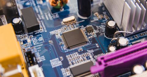
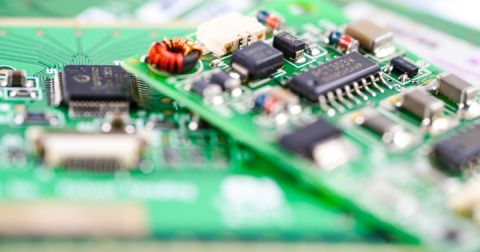
In an era when electronics are becoming more compact, powerful, and interconnected, complexity isn't just growing. It's compounding. Designers today aren’t just building single PCBs. They’re orchestrating full-blown electronic ecosystems where multiple boards must work in perfect harmony. Multi-board design is the new normal, whether it's a high-speed compute module connected to a power conversion board or a sensing PCB feeding into a communications backbone. But our design workflows? They’re still stuck in the past.

The Status Quo: Disconnected Tools for Multi-Board Connected Systems
In the traditional design flow, each board is often treated as a silo. Schematics are designed individually, the layout is done without full system context, and mechanical fit checks are usually left to late-stage assembly prototypes—if they’re done at all. Cross-functional collaboration between ECAD and MCAD teams feels like passing notes across enemy lines, and simulation is something you “get around to” once the design is almost done.
The result? Misaligned connectors. Cables that don’t reach. Power budgets that don’t balance. And design teams are stuck in a costly cycle of prototype-test-redesign-repeat.
Let’s face it. Today’s disconnected toolchains weren’t built to handle the systems-level thinking that modern hardware demands.
The Pain: Why the Old Way Fails
1. Integration Risk is High
You’re integrating boards with different designers, constraints, and often different design philosophies. The likelihood of interconnect errors—wrong net assignments, mismatched pin mappings, overlooked grounding schemes—is enormous.
2. Mechanical Fit Is an Afterthought
Without native 3D multi-board visualization, detecting physical clashes between stacked or folded PCBs often comes too late. Enclosures don’t close, ports don’t align, and thermal management? That’s another fire drill waiting to happen.
3. Simulations Come Too Late
Power and signal integrity simulations are typically relegated to post-layout phases when changes are costly and disruptive. Yet, as designs grow more power-dense and electrically sensitive, early simulation is no longer optional. It’s mission-critical.
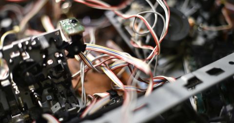
4. Wiring and Harness Designs Are Manual and Error-Prone
In multi-board systems, what connects the boards is just as important as what’s on them. However, many teams still design cables and harnesses manually using Excel or out-of-sync mechanical models. That’s a recipe for expensive miscommunication.
The Shift: Why Altium Changes the Game
Enter Altium—a unified design environment that supports multi-board design and actively enables it. This isn’t an afterthought or a bolt-on module. It’s system-level thinking baked into the platform's core.
Multi-Board Design Made Native
Altium’s Multi-Board Assembly Editor allows you to logically and physically define how your boards relate to each other. You create a multi-board schematic to manage interconnects like in a single-board design. From there, you launch a 3D multi-board assembly workspace where you can rotate, align, stack, or fold PCBs into their final physical configuration.
This means that even in early design stages, you can visualize how your boards will physically interface, catching clashes, alignment issues, or mechanical inconsistencies before they hit the production floor.

Real-Time Validation at the Multi-Board System Level
Altium incorporates robust error-checking mechanisms that operate in real-time. As designers work on multi-board assemblies, the software continuously monitors for potential issues, such as interconnect mismatches or mechanical collisions. Immediate feedback allows for prompt corrections, reducing the risk of errors propagating to later stages of development.
Advanced Simulation Capabilities
With the integration of advanced simulation tools, such as the Power Analyzer powered by Keysight, Altium empowers engineers to perform comprehensive power analysis directly within the design environment. This capability allows for the early detection of potential power integrity issues, enabling designers to make informed decisions and optimize performance before proceeding to manufacturing.

MCAD CoDesign, Done Right
Recognizing the importance of mechanical integration, Altium offers seamless collaboration between electronic and mechanical design domains. The MCAD codesign ensures that any changes made in the electronic design are accurately reflected in the mechanical design and vice versa. This bidirectional communication streamlines the design process, ensuring all components fit together as intended and reducing the likelihood of mechanical conflicts.
Harness Design Integration
Altium extends its capabilities to include comprehensive harness design tools. Engineers can design and document complex wiring harnesses within the same environment, ensuring that all interconnections between boards are accurately represented and that the physical implementation aligns with the design intent. This integration simplifies the design process and enhances the reliability of the final product.

The Outcome: Confidence, Not Guesswork
With Altium, you’re not just designing PCBs. You’re engineering entire multi-board systems with the precision and foresight required in today’s high-stakes hardware world. The platform brings together electrical, mechanical, and systems-level views in one place, enabling design teams to iterate faster, collaborate tighter, and validate sooner.
In short, Altium takes the chaos of multi-board design and transforms it into clarity.

Final Thought
In the words of product managers everywhere: “If it doesn’t integrate, it doesn’t ship.” Whether you're building next-gen wearables, modular industrial controls, or complex embedded multi-board systems, seamless multi-board integration is no longer optional. Altium rises to the occasion by providing a unified platform that addresses the multifaceted challenges of modern electronic design. Altium empowers engineers to navigate the complexities of multi-board integration with confidence and efficiency by streamlining processes, enhancing collaboration, and ensuring design accuracy.
Interested in exploring multi-board PCB design? Discover how Altium Develop makes it easy to create complex designs and error-free system interconnections.
About Author
Related Resources
Related Technical Documentation
Table of Contents
- The Status Quo: Disconnected Tools for Connected Systems
- The Pain: Why the Old Way Fails
- 1. Integration Risk is High
- 2. Mechanical Fit Is an Afterthought
- 3. Simulations Come Too Late
- 4. Wiring and Harness Designs Are Manual and Error-Prone
- The Shift: Why Altium Changes the Game
- Multi-Board Design Made Native
- Real-Time Validation at the System Level
- Advanced Simulation Capabilities
- MCAD CoDesign, Done Right
- Harness Design Integration
- The Outcome: Confidence, Not Guesswork
- Final Thought
Design to Release, Without the Friction
- Keep reviews tied to the right version
- Reduce handoff confusion and rework
- Spot sourcing and release risk earlier
- Work solo, share when needed
Get Started
Thank you, you are now subscribed to updates.