Switchback Routing vs. Serpentine Traces Routing for Maximum Density

Ever drive through a winding mountain pass? When I was a student, there was one back road that would wind back and forth as you ascended a small mountain. This style of paving roads is also used to route traces in PCBs. This routing style, called switchback routing, can be used for length matching/delay matching in replacement of, or alongside, other length tuning styles.
With all the different length tuning and routing styles available in PCB design tools, it may not be obvious when switchback routing is a better choice than other length tuning styles. In fact, some component manufacturers explicitly recommend using switchback routing or trombone routing with their components. Let’s take a look at switchback routing and layout styles and some of the benefits they provide.
What is Switchback Routing?
Switchback routing is a PCB trace layout and length tuning style that incorporates a number of U-turns in the trace as it is routed towards its destination. Switchback routing is sometimes called accordion routing or trombone routing. It is also sometimes used interchangeably with serpentine routing. If you look at some switchback routing styles, you will see some interesting back-and-forth trace patterns that do not resemble the typical trombone and serpentine routing styles.
The closest substitute for switchback routing is the typical serpentine routing style, where traces are meandered transverse (perpendicular) to the trace direction. In switchback routing, successive U-turns are used to meander the trace length in the longitudinal direction, rather than in the transverse direction as is the case in serpentine routing. High-quality CAD tools will allow you to use either style of routing to increase trace density, or for delay/length tuning parallel signal nets.
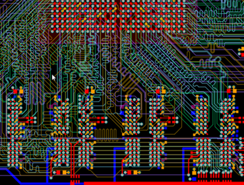
Each routing style provides some particular benefits in terms of coupling, trace density, and signal integrity. For highly complex boards, it is not uncommon to find a mix of serpentine, trombone, and switchback routing styles in an effort to pack traces into the smallest possible space. The image below shows just such a mix of these different routing styles for an LPDDR3 memory interface.

When to Use Switchback Routing vs. Serpentine Routing
If you look through some application notes for different components, or some design rules, you might find some guidelines for sizing a switchback routing pattern. Some of these application notes will explicitly state that you must use switchback routing (rather than some other length tuning style) to ensure length matching and delay matching at the receiver for differential pairs or across a parallel interface.
Advantages of Switchback Routing
One primary advantage of switchback routing compared to serpentine routing is that it allows compensation of skew with a shorter required length match. The example image below shows length-matched switchback and serpentine routing patterns. These two patterns are designed to compensate for the same amount of skew while ensuring maximum routing density by staggering the length matching segments. The switchback pattern requires a shorter total length than the serpentine pattern for a given level of skew compensation requirement.

For length-matched parallel buses, you'll usually use a mixture of the two approaches in order to keep the overall routing area for the bus reasonably small, such as the parallel interface routing shown above.
Disadvantages of Switchback Routing in Differential Pairs
Note that switchback routing is not always the best choice for differential pairs, especially when the pairs are closely spaced together and the ground reference is farther away in a thicker dielectric. While you can keep the total length of the route shorter, each section used for length matching applies an impedance discontinuity, and the magnitude of the discontinuity depends on the spacing between the straight sections of the differential pair. Inside the length-tuned section, the odd-mode impedance in that section will be slightly higher than in the closely-spaced sections.
I've discussed the reasons for the odd-mode impedance deviation in this article.

There is also a problem of mode conversion, which will occur any time you have an asymmetry along a differential pair. Within the switchback region, the required coupling switches between differential mode and common mode as the signal traverses the switchback region. Mode conversion causes some common-mode noise to appear as differential-mode noise at the receiver, and this amount of conversion gets larger at higher frequencies.
If any noise is induced in the switchback region, it may not be seen as common mode noise at the receiver. Even in the case where the switchback regions are not staggered, tight coupling is difficult to maintain unless the switchback regions are routed closely together and track each other throughout the length of the pair. Using a serpentine length tuning scheme to match traces in a differential pair is a better choice than serpentine unless available space along the route is a challenge. You’ll sacrifice density in exchange for greater common mode noise suppression and less mode conversion.
In General, Keep Length Tuning Minimal
To brielfy summarize, there are two reasons to keep length tuning sections short wherever possible:
- To maintain consistent impedance across the entire length
- To prevent mode conversion
Either of these effects can be seen in the time domain using a time-domain reflectometry (TDR) trace or in simulation results. Any field solver that works directly from your layout data can show you this effect. In a TDR trace, a capacitive impedance discontinuity can be seen at the structure due to reflections. Decreasing the spacing between each switchback section will increase this capacitive impedance discontinuity. This point, as well as distortion produced in switchbacks, should illustrate the complex nature of these structures and the various tradeoffs involved in switchback routing:
- Shorter delay structures reduce distortion, but there is a larger impedance discontinuity when the pitch between each U-turn is smaller.
- A delay structure can be made longer with lower spacing to reduce an impedance discontinuity, but there may be some level of distortion.
Obviously, these factors are in competition with the need to reduce skew and ensure signal swing matching. There could be additional skew that arises between the two traces of a differential pair, but by closely length matching you will ensure that the link will still survive this additional skew.
Crosstalk in Single-ended Switchback Structures
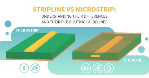
Obviously, both serpentine and switchback routing styles include the same U-turn structure, and the length tuning region can act as a coupling area for both near-end crosstalk (NEXT) or far-end crosstalk (FEXT) as a fast signal enters the delay structure. NEXT has a limited coupling region in both microstrips and striplines, but in both cases, applying a length tuning structure can reduce the distance between the two nets. The result is strong crosstalk in that area. If the signal is fast enough, and if the coupling region is long enough, coupling could produce maximal crosstalk in that region.
This is another reason it is better to route differential pairs over thinner dielectrics with a ground reference on the adjacent layer. Although you can technically route a differential pair above a region without ground as long as the pairs are closely spaced, the ground plane provides an important function of reducing the trace inductance, and thus the inductively-coupled portion of crosstalk. This applies in any kind of routed structure (switchback or serpentine).
The routing and crosstalk tools in Altium Designer® are an excellent set of features for implementing switchback routing and examining any effects of NEXT in your switchback designs. The time-based length tuning features are ideal for delay matching multiple signals and ensuring they stay synchronized throughout your board. You’ll also have access to a powerful set of schematic design tools, CAD features, and production planning tools.
Now you can download a free trial of Altium Designer and learn more about the industry’s best layout, simulation, and production planning tools. Talk to an Altium expert today to learn more.


