


Do You Know How to Prevent Voltage Fluctuation?


One of the most common types of power supply issues is output voltage fluctuation. This problem is caused by various factors, including input voltage variations, unpredicted changes in the load current, feedback control loop malfunctions, switching frequency issues, component tolerances, temperature variations, and aging components.
This article will briefly explore the causes of output voltage fluctuation and provide insights on how to solve and prevent these issues.
Input Voltage Variations
The input voltage to the power supply (or the regulator chip) could fluctuate to exceed the regulator chip's absolute maximum/minimum limits. The regulator/controller chip is not able to handle these variations, and depending on the frequency of the variations, the output voltage might drop, increase, or demonstrate a significant amount of ripple.
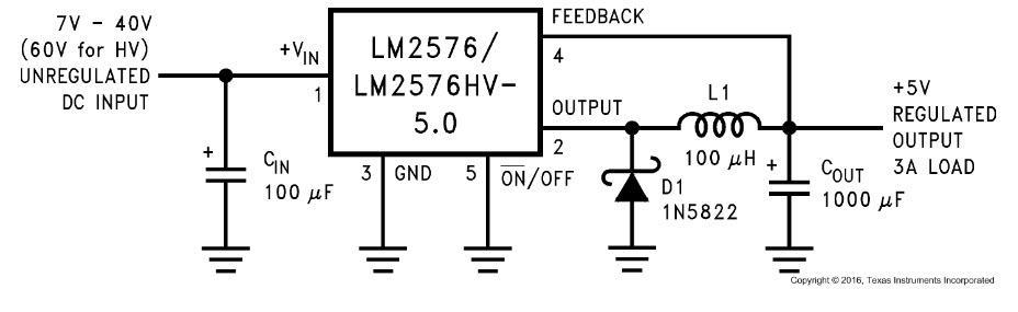
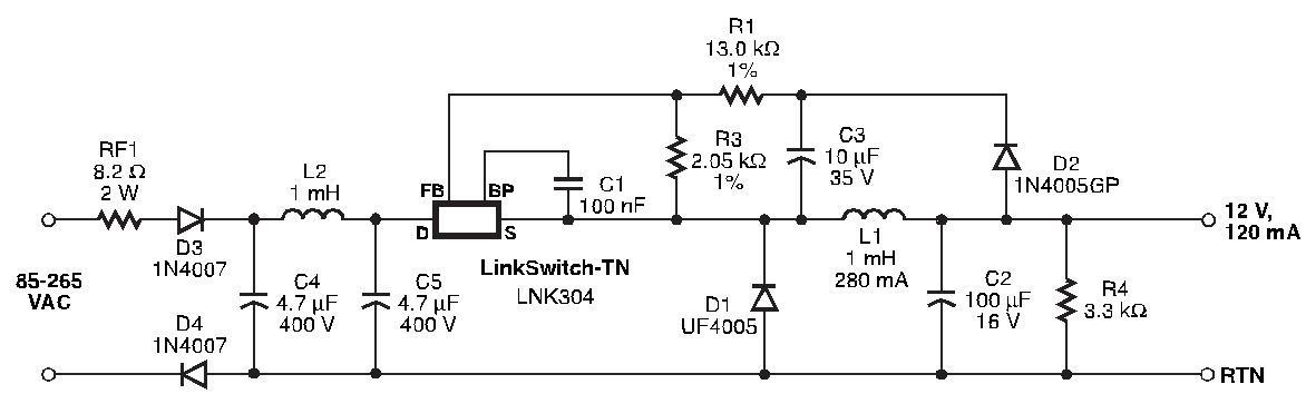
For example, please look at the application diagram of the famous LM2576-5.0 [1] regulator chip by Texas Instruments (Figure 1). It is clearly stated that the input voltage variation range could be somewhere between 7-40V (60V for the HV version). Another example is the LNK30X chip, by Power Integrations (Figure 2) [2]. Here, It is mentioned that the input AC voltage should not rise above 265VAC, and not fall below 85VAC. Otherwise, the output voltage could fluctuate, especially under some load.
It should be noted that a power supply might not be able to handle sudden, significant voltage variations at the input, even if the variations fall within the minimum/maximum range. This can also cause the output voltage to fluctuate.
Figure 1
Application diagram of the LM2576-5.0 buck converter chip
Figure 2
LinkSwitch-TN Universal Input, 12V-120mA output
Load Changes
The power supply might not be able to handle sudden changes in the load current, which leads the output voltage to fluctuate. For example, if the current delivery of a power supply is rated at 3A maximum, and the load suddenly draws 4A, if this happens periodically, then it will lead the output voltage to drop and fluctuate.
Furthermore, even if the load’s current only varies within the limited range, the power supply must be tuned and tested against the “load step response”, using a DC load. To put it simply, a DC load applies load pulses periodically (for instance: low current level: 1A, high current level: 3A) to the supply output while the output voltage is monitored for any ringing. This is an essential test for the applications where the load current might be changed significantly and frequently, such as a car where the driver might turn ON/OFF the headlights, heating elements, ... etc. quite often. Figure 3 shows an untuned power supply [3]. Figure 4 shows a modified/tuned power supply [3] that passes the load step response test.
Figure 3
Untuned power supply (Pink: Current Pulse, Yellow: Output Voltage, Orange: Output Voltage (4P-Averaging)
Figure 4
Tunned power supply (Pink: Current Pulse, Yellow: Output Voltage, Orange: Output Voltage (4P-Averaging)
Feedback Control Loop
This is the most probable reason behind all output voltage fluctuations! So you should check for this first before looking for other possible output voltage fluctuation problems. A feedback control loop is simply a circuit path for the controller/regulator to sense the output and stabilize the voltage. Any malfunction in the feedback circuit will, at the least, lead to output voltage fluctuation.
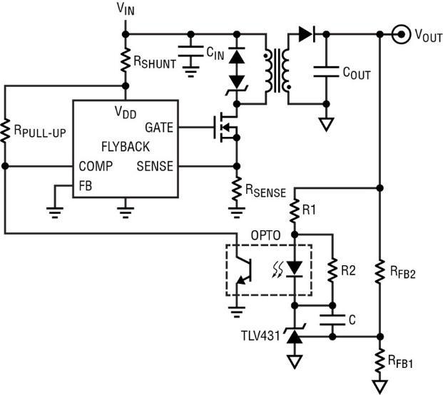
The feedback path is easy to spot in the linear and buck/boost voltage regulator circuits. For the flyback converters, the minimum components of the feedback control loop are the optocoupler and Zener diode (or a shunt regulator) (figure 5). The output rectifier diode and filtering capacitors also play a significant role in stabilizing the control loop, which will be discussed in the “aging of the components”.
Figure 5
A typical circuit of a flyback converter
Switching Frequency
If you design/repair a power supply and the output voltage is unstable, then one probable reason could be an incorrect switching frequency. The switching frequency plays a very significant role in calculations and component values. A significant drift from the calculated frequency or any instability can cause the output voltage to fluctuate.
Component Tolerance
Power supplies are made up of various discrete components, and their tolerances should stay within an acceptable range, 5% tolerance, for instance. If these components demonstrate a higher tolerance or if you use low-quality components, it can cause the output voltage to fluctuate or degrade in efficiency. Therefore, if you design your power supply, you should stay as close to your calculated values as possible. In case of a repair attempt, replace the faulty component with an identical one (value, size, tolerance).
Temperature Variations
Naturally, power supplies generate heat, therefore this heat must be dissipated properly using heatsinks and fans. Otherwise, the extensive heat imposes thermal stress on the components and reduces their lifespan, which easily causes the output voltage to fluctuate. Moreover, if the ambient temperature of the application environment is high or if there is no proper ventilation, this can also lead to voltage fluctuations because the components cannot cool down properly.
Aging Components
Over time, the performance of components -especially electrolytic capacitors- may reduce, leading to failure. Most of the time, it’s obvious when an electrolytic capacitor changes its shape or it looks bulgy, but sometimes they get dried out without any visual signs. Bulging or dried output capacitors are one of the most common reasons for output voltage fluctuation because failed capacitors affect the performance of the feedback control loop and increase the output ripple/noise.
Apart from this, the main input capacitor (after the bridge rectifier) or decoupling capacitors of the controller chip might fail and affect the output voltage. As a rule of thumb, any capacitor that has lost over 20% of its original capacitance value should be replaced. So an LCR meter is a must-have tool for any power supply design or repair attempt.
This video explains three ways to test for an electrolytic capacitor failure [4], without measuring the ESR. If looking for and repairing individual electrolytic capacitors is too time-consuming, then replacing all electrolytic capacitors might be a wise decision! Figure 6 shows a bulging capacitor.
Figure 6
A bulging electrolytic capacitor
References
[1]: LM2576: https://www.ti.com/lit/ds/symlink/lm2576hv.pdf
[2]: LNK30X: https://www.powerint.cn/products/linkswitch/linkswitch-tn/lnk304dg
[3]: Load Step Response with a SIGLENT DC Electronic Load: https://www.siglenteu.com/application-note/power-supply-design-load-step/
[4]: How to Easily Detect a Failed Capacitor: https://www.youtube.com/watch?v=XKv4OMSz7jU

About Author
Related Resources
Related Technical Documentation
Table of Contents
Design to Release, Without the Friction
- Keep reviews tied to the right version
- Reduce handoff confusion and rework
- Spot sourcing and release risk earlier
- Work solo, share when needed
Get Started
Thank you, you are now subscribed to updates.

