


A Guide to PCB Power Supply Layout

At a Glance
Follow this quick guide to using linear power supplies and switch-mode power supplies in your next PCB design.


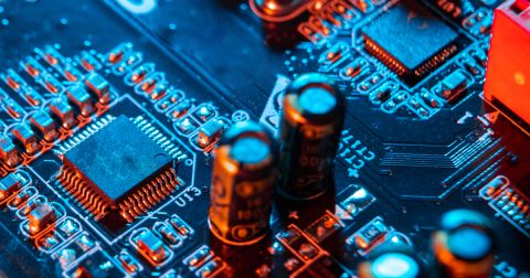
Power supplies are essential in most PCB designs, but they often introduce unique challenges. When planning your layout, you’ll need to choose between two key options: linear and switch-mode power supplies. Each type presents distinct challenges for your design, from efficiency to heat management. Understanding how these power supplies impact your PCB layout will help you create a more reliable, efficient design, and overcome common obstacles in power management.
Linear Power Supplies
Linear power supply circuits are straightforward with minimal components, but their inefficiency results in significant power loss, primarily as heat. Managing this thermal energy becomes a challenge, especially when dealing with temperature-sensitive components or when the PCB is enclosed in sealed cases that limit cooling options.
Switch Mode Power Supplies
Switch-mode power supply circuits are more complex than linear ones but are significantly more efficient. This reduces the need for extensive thermal management but introduces electromagnetic noise, which can interfere with other PCB elements and even nearby devices. The switching circuit has the potential to generate significant levels of electromagnetic noise that the PCB designer will need to manage. In extreme cases, the noise generated by the PCB power supply circuit can be conducted back through the mains electricity supply wiring to affect other devices connected to the same mains supply.
Another potential noise issue is that switch mode circuits tend to generate a ripple voltage on the output that can if not correctly managed, induce interference on the board through capacitive or inductive coupling between tracks running in parallel or bundled wires. A final and more subtle problem is the potential for a ground bounce on the PCB where the switching circuit is mounted. Rapid switching can cause a transitory change in the ground potential at the point in the board where the switching components connect to the ground plane. This results in a temporary potential difference across the board’s ground plane. In an extreme case, the difference may result in components in a distant part of the board observing and reacting to a perceived signal resulting from this false potential difference.
PCB Layout Power Supply Guidelines
Grounding
Unless space is constrained, allow for a board design to include a solid power supply ground plane to provide electromagnetic shielding. If devoting a whole layer is not possible, consider as a minimum a ground polygon that covers the entire area under the PCB power supply components.
The ground plane for the PCB power supply design should be separated from the common ground for the rest of the circuit to minimize noise coupling effects. In addition, the connection between these two grounds should be limited to one point on the board to prevent ground loops.
Trace Conductivity
Keep traces for PCB power supply circuits as short and broad as possible to reduce resistive losses and electromagnetic noise emissions. Where space allows, the recommendation is to use polygon pours. This is particularly relevant for linear power supplies where thermal conductivity can be critical.
It would be best to include solid fill internal layers that use vias for connection for power and ground planes in the board design for maximum effect. Using vias to switch PCB power supply traces from one layer to another should be avoided as the via will act as a point of increased impedance. Multiple vias linking polygons offer a better solution.
The performance will be affected by the thickness of the copper layers, though increasing thickness carries a price premium, so a trade-off between cost and performance may be necessary.
Another option for increasing conductivity is to add a solder layer to the outer board layers through changes to the solder mask. However, you can obtain better performance by adding PCB bus bars or external wires between the points on the board where PCB power supply design components are mounted.
Component Placing
Driven by the requirement for traces to be as short as possible, PCB power supply components should be located as close together as possible in the optimum orientation to achieve short trace lengths. This can include mounting parts on both sides of the board to achieve this.
Trace Routing
Traces carrying sensitive signals should ideally be routed away from power supplies on an unconnected board layer separated from the 12V power supply PCB layout design traces by a ground plane. Signal traces should never run parallel to power traces carrying power to prevent noise-coupling from the layout power supply to the signal. If proximity is unavoidable, signal traces should cross PCB power supply traces at 90 degrees to minimize noise coupling effects.
Thermal Management
All layout power supply circuits generate heat, so the board design will need to include thermal management. Therefore, the first layout consideration should be component placement to separate heat-generating components from heat-sensitive components if possible while maintaining short trace lengths.
The next consideration is using the copper of the board to provide thermal conductivity to distribute heat more evenly away from hotspots and to areas that allow heat dissipation.
A potential issue for switch-mode PCB power supplies is that the feedback control circuit often contains temperature-sensitive components that need colocation with the heat-generating switching components. If unchecked, hot spots can cause layout power supply instability and exacerbate thermal issues.
Summary
Power supplies can be the source of most thermal and noise issues in a PCB, so the board design must consider this from the start. A good board design starts with a good PCB power supply layout.
Whether you need to build reliable power electronics or advanced digital systems, Altium Develop unites every discipline into one collaborative force. Free from silos. Free from limits. It’s where engineers, designers, and innovators work as one to create without constraints. Experience Altium Develop today!
About Author
Related Resources
Related Technical Documentation
Table of Contents
Design to Release, Without the Friction
- Keep reviews tied to the right version
- Reduce handoff confusion and rework
- Spot sourcing and release risk earlier
- Work solo, share when needed
Get Started
Thank you, you are now subscribed to updates.

