Pros and Cons of Orthogonal Trace Routing in Multilayer PCBs

I occasionally see questions on forums, some blog posts, and even application notes that continue to recommend the use of orthogonal routing, usually in 2-6 layer boards. When looking at application notes, I tend to default to Rick Hartley’s advice and try to think about this advice in context. Unfortunately, recommendations in application notes are not always taken with a grain of salt, and they are often applied in situations where they are not applicable.
This article is more about when not to use orthogonal trace routing, rather than how it can be configured in an autorouter or a similar topic. If you’ve worked in the ultra-high speed/high frequency world for a long period of time, then this is most likely not new to you. For the rest of us, there is a temptation to default to old information that is often provided without context. This is especially true of orthogonal trace routing.
Bad Stackups Lead to Crosstalk in Routing
I think the first time I saw a recommendation that designers use orthogonal routing was on StackExchange. This website is an excellent resource on many topics, and it is definitely my go-to resource for all things related to software and coding. With electronics and PCB design becoming ever more complex, it is easy to apply recommendations from this site and others without considering context, leading to cases where these design choices cause a board to fail.
I recently had a client looking for some help debugging an upgrade to an older design. The client decided to use the classic orthogonal trace routing recommendation with the 6-layer stackup shown below. In this stackup, the two top layers and two bottom layers are signal layers. Traces in these layers were routed orthogonally between ICs, and standard through-hole vias were used for layer transitions.
Don’t use this simple 6-layer stackup with high speed signals...
The experienced designer should already have an idea of what is wrong with this picture. The problem was that the engineer was trying to upgrade the design to use a new MCU that runs at 400 MHz with high speed interfaces but without changing the stackup; the design had excessive crosstalk and did not pass EMC testing.
At this point, the solution should be obvious; design the stackup properly and you won’t have to rely purely on orthogonal routing to ensure signal integrity when working with high edge rates. As it turned out, this ended up being a power integrity problem, which has less to do with orthogonal routing and more to do with layer arrangement. However, this begs the question: when should you use orthogonal routing?
When is Orthogonal Trace Routing Applicable?
Orthogonal routing is used in two possible situations:
- To carve out vertical and horizontal routing channels in different layers
- To prevent capacitive crosstalk between traces on adjacent layers by minimizing the couple area between them
The first usage is totally appropriate and it can make routing much easier, as long as the stackup is designed correctly (see below).
Regarding signal integrity, you have the following progressively difficult crosstalk problems when you use orthogonal routing between two adjacent signal layers:
- At low edge rates, there will be less crosstalk anyways, even in adjacent signal layers (applicable to UART, I2C, etc.)
- At faster edge rates (such as SPI), you may notice crosstalk in more advanced chips
- In differential pairs, the crosstalk will be differential, which cannot be canceled at a receiver
- At very fast edge rates (sub-ns), you will notice more crosstalk and radiated emissions
How is this supposed to work for signal integrity? As an aggressor digital signal propagates, it generates a magnetic field, and the switching edges of the signal will generate a changing magnetic flux in the region around the trace; this is inductive crosstalk. There is also an electric field between the two lines; when the aggressor signal switches, it induces a displacement current in the victim line; this is capacitive crosstalk.
When interconnects on adjacent layers are routed orthogonally (along perpendicular directions), the magnetic field from one trace will always be oriented parallel to the conductor loop formed by a victim trace on the next layer, effectively eliminating direct inductive crosstalk. While this description is technically correct, it is overly simplistic and does not account for other important aspects of a real PCB stackup and layout. The primary problems involved in using orthogonal routing relate to switching speed, decoupling, and defining a reliable return path. Rick Hartley discusses some of these important routing and stackup aspects in a recent interview.
Despite the lack of inductive coupling, there is still capacitive coupling, even with the small intersecting area between traces. If you haven’t properly designed your return path, the electric field between signal layer 1 and its ground (see the above image) can couple back to signals in layer 2 simply due to a potential difference across their mutual capacitance, producing capacitive crosstalk. The impedance seen by the capacitively coupled signal is lower when the signal edge rate is faster, producing a stronger current pulse in the victim trace.
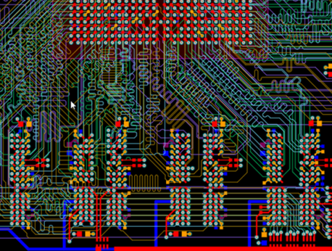
Advanced designs like this won’t use orthogonal trace routing.
At lower edge rates, you probably won’t notice capacitive crosstalk, regardless of whether orthogonal routing is used. It will still happen, but it might not be sufficiently large to break through the noise margin of any components connected to victim traces. At low speed, inductively coupled signals see lower impedance, thus you would want to route orthogonally on adjacent signal layers in order to minimize inductive coupling. Working with low edge rates is one instance where orthogonal trace routing in adjacent signal layers is appropriate.For the rest of us, we’re usually working under a nanosecond in terms of edge rate, which requires careful shielding/isolation between signal layers, a carefully engineered return path, and ultra-stable power delivery. It all hinges on designing the right PCB stackup.
Route Orthogonally, But Use Ground
The takeaway here is simple: orthogonal routing is not a cure for signal integrity problems, specifically crosstalk with fast edge rates. However, orthogonal routing is very useful simply for carving out channels between groups of components. In order to use it properly, the stackup needs to have ground separating the two signal layers.
In the example below, I'm showing one of our legacy multilayer designs with a signal layer on the outer surface. L2 is ground and L3 contains the orthogonal routing channel. Together, this type of routing in two perpendicular directions creates a superhighway for your routes in different layers. The routing is very clean, being broken into two different channels that can be accessed easily with through-hole vias coming off components on both sides of the board. This makes it easy to route between the central MCU and the RAM chip at the top of the board.

The stackup is shown below. This stackup uses two internal signal layers, but L4 was allocated to control pins and power rails. Note that you could implement the same routing style on a 4-layer board with two internal ground planes. The main guideline here is that orthogonal routing is fine, as long as ground separates the two signal layers.

This puts the emphasis on smart component placement in the PCB layout, especially of connectors. However, you don't always have the freedom to place connectors wherever you want. In a real product, you may be constrained by cables entering the enclosure, other boards in the enclosure, odd pinouts on components, and odd pinouts on connectors. The connector issue is probably the biggest challenge as it can seriously constrain routing, especially when the pinout is standardized or when the pinout is constrained by some other product. In this case with connectors, if you can get control of the pinout through custom cable/harness design, you can more easily implement an orthogonal routing strategy.
The routing and layer stack design features in Altium Designer® are the go-to choice for creating your board and your layout. The rules-driven design engine provides return path checking and other important DRCs as you create your layout. You’ll be able to design top-quality PCBs for any application. You can also simulate various aspects of signal behavior with the post-layout simulation tools in Altium Designer.
Now you can download a free trial of Altium Designer and learn more about the industry’s best layout, simulation, and production planning tools. Talk to an Altium expert today to learn more.

