Differential Stripline Impedance Calculator
If you’re not in the mood to calculate differential stripline impedance by hand, you need a tool that gives you accurate results without too much complexity. We created a simple calculator you can use to estimate differential stripline impedance as long as you know a value for your substrate dielectric constant. If you’ve been looking for an accurate differential stripline impedance calculator that can work with your trace geometry, then the calculator below is an excellent free tool to help you get started. Once you’ve finished before you start using field solvers to determine differential pair impedance.
Differential Stripline Impedance Calculator
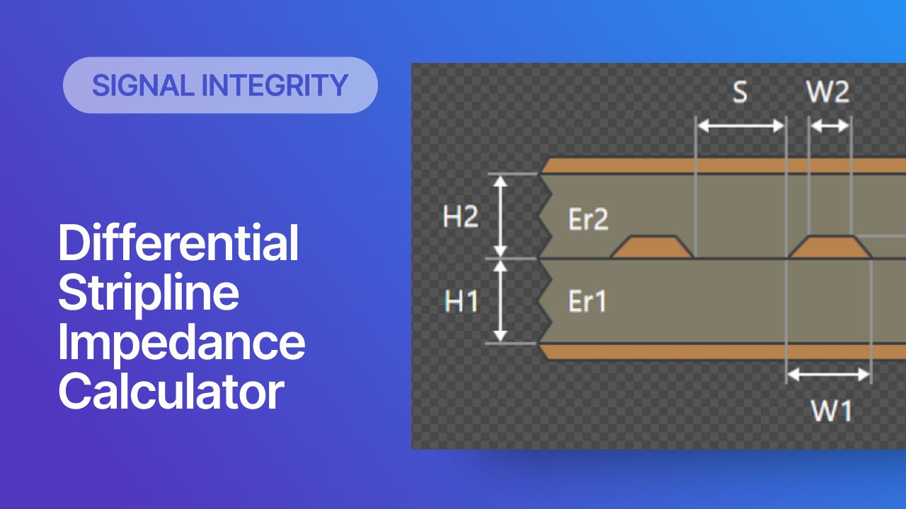
A differential stripline pair refers to two traces located between two reference plane layers, which are routed as a differential pair. This calculator determines the impedance of a symmetric differential stripline pair. This calculator requires symmetry in the trace widths and location between plane layers. The calculator below uses Wadell’s equations to determine the differential impedance of symmetric striplines, which can be found in the seminal textbook Transmission Line Design Handbook.
The equations that are used to calculate stripline impedance are simple, but there is a large number of terms, which includes a requirement to calculate elliptical integrals to solve these equations. The calculator below automates this for you, giving you the differential impedance for the pair and the odd-mode impedance for a single trace.

Results
To learn more about trace impedance calculators, Wadell’s equations, and some drawbacks of impedance calculators, read this article on single-ended stripline impedance calculators. You can also read this article by Jason Ellison to learn more about differential stripline impedance estimation and the underlying methods used in differential impedance calculations.
Differential striplines are quite interesting in that they can be much narrower than microstrips in the same material due to the required coupling from the adjacent reference planes. The nearby ground planes will be the dominant factor determining the impedance whenever the planes are close to the traces. This requires you to route the traces farther apart in order to hit a standard 50 Ohm impedance goal. The solution built into the above calculator enforces the limit (S/T) > 5 in order to ensure a result is returned. This preserves the accuracy of the result based on the approximation applied in the calculation.
Where Do Analytical Impedance Calculators Fall Short?
Impedance calculator tools are very useful for understanding how geometry affects the impedance of differential microstrips. However, there are many important pieces of information that are not included in a typical differential microstrip impedance calculator:
- Dispersion - The dielectric constant will be some function of frequency, but this is not included in the above calculation. Instead, the calculator assumes that you know the correct value of Dk needed for your particular frequency. Learn More.
- No dielectric losses - The corresponding point to the above remarks about dispersion is that simple calculator applications can only take the real portion of the dielectric constant as an input, but the loss tangent is omitted. Learn More.
- Copper roughness - The roughness of the copper layer will have some contribution to the impedance, and this needs to be included in designs operating near WiFi frequencies or higher. The function of copper roughness is to increase the magnitude of the skin effect. Learn More.
- No etch factor - The etching process does not create truly rectangular traces, but rather a finished trace will have a trapezoidal shape. This will cause a real trace to have a slightly different impedance value than what would be calculated in the type of calculator shown here. Learn More.
- No propagation delay - If you use an online calculator to determine impedance, you usually won't be given a propagation delay value. You'll have to calculate it using the speed of light, or your calculator will just give a standard value for FR4 that is known to be incorrect. Learn More.
More Accurate Results Require a Field Solver
Differential stripline impedance calculators like the one shown here are useful for getting an initial estimate of trace impedance for a particular geometry. Think of them as an order of magnitude estimate; you will usually get decent accuracy, but the results are not precise for the reasons listed above. To fix these problems, you need a model that can account for losses and the real characteristics of PCB dielectric materials, namely loss tangent and dispersion. This problem would normally be approached with a field solver that can calculate the characteristic impedance and the coupled (differential) impedance based on the cross section of the trace and spacing between traces.
When you need a highly accurate differential stripline impedance calculator, use the Layer Stack Management in Altium. This tool includes a field solver that is built into the PCB Editor, giving highly accurate impedance results that account for losses in real PCB materials. You can then create a design rule that applies the impedance calculation results to your trace geometry, and this will be enforced automatically as you route the PCB.

The built-in layer stack editor in Altium can act as your powerful differential stripline impedance calculator, both for standard striplines and coplanar arrangements. When you’re ready to release these files to your collaborators for more advanced simulations, Altium makes it easy to collaborate and share your projects. Everything you need to design and produce advanced electronics can be found in one software package.


