FR4 Dielectric Constant and Material Properties

High-speed and high-frequency boards need accurate dispersion calculations to ensure signal integrity and accurate propagation delay. FR4 is the most popular type of PCB laminate, and its material properties are well-documented. We’ve compiled the important material properties for FR4, including FR4 dielectric constant, thermal conductivity, and more. Altium Designer includes an accurate wideband Debye model calculation for FR4 dielectric constant and the tools you need for high-speed PCB design.
ALTIUM DESIGNER
The most powerful, modern, and easy-to-use PCB design tool for professional use.
Your PCB design begins with an insulating substrate, typically made from a material called FR4, as its core. The designation “FR4” refers to the flame-retardant properties of the dielectric material and type-4 woven glass-reinforced epoxy laminate used to build up the substrate. This type of laminate material is highly insulating and rigid, and every manufacturer should know how to work with FR4 laminates as a base material.
An important part of designing PCBs on an FR4 laminate material is to understand its material properties, which includes its dielectric properties and thermal properties. With the right design software and materials stackup library, you can define an accurate impedance profile for your high-speed PCB and run accurate signal integrity simulations. Altium Designer provides the stackup design tools you need to include FR4 dielectric constant and thermal properties in your simulations, as well as many other features for designing your next high-speed PCB.
Understanding FR4 Dielectric Constant and Dispersion
All materials have some electric permittivity—a characteristic that describes the speed that an electrical signal travels through a material and the amount of electrical charge that material can store in a given volume. The electric permittivity of free space (vacuum) is:
Ɛ0 = 8.854 x 10⁻¹² Farads/meter
Signal propagation speed occurs relative to the speed of light in a vacuum, which is defined in terms of a relative permittivity, or dielectric constant. The dielectric constant of FR4 ranges from 3.8 to 4.8, depending on the glass weave style, thickness, resin content, and copper foil roughness.
In addition to the dielectric constant of FR4 materials, the arrangement of traces and planes on a PCB laminate determine the effective dielectric constant for signals traveling in an interconnect. Signals traveling on surface microstrip traces or coplanar waveguides will have speed that is determined by some effective dielectric constant, which then depends on the geometry of a trace. In order to determine the appropriate impedance and propagation velocity for signals on a PCB trace, your PCB design software needs to include a stackup design utility with data for a range of standard PCB laminate materials, including FR4.
|
Flammability rating |
UL94-V0 |
|
Dielectric constant |
3.3-4.8 (depends on weave style, resin content, and material composition) |
|
Breakdown field strength |
Approximately 20 kV/mm |
|
Standard thickness |
1.57 mm |
|
Glass transition temperature |
~130 °C (low-Tg laminates) or ~170 °C (high-Tg laminates) |
Dissipation in FR-4 Dielectric Constant
The limitations also become apparent when using standard FR4 materials with RF applications. On one hand, dielectric stability may suffer across the higher frequencies. Along with a higher dissipation factor (Df) and higher insertion losses at microwave frequencies of 1 GHz to 15 GHz, traces used on FR4 have a larger attenuation at RF frequencies. Further, the FR4 thickness affects the effective dielectric constant of the PCB and…the greater impedance matching required for RF circuits. When working with RF circuits, the selection of high-performance FR4 that can handle multiple lamination cycles and has good reliability characteristics works as a solution for those problems.
- Measurements of FR4 dielectric constant can be difficult as the results will vary with respect to the measurement method.
Learn more about FR4 dielectric constant and alternative substrate materials.
- Impedance calculations for common trace geometries, such as microstrips and striplines, require accurate wideband Debye dispersion models for FR4 dielectric constant.
- Balancing FR4 dielectric constant with PCB laminate thickness and trace width is a difficult problem, but the right stackup manager can help you produce accurate impedance and propagation delay calculations.
Learn more about optimizing trace widths and propagation delay with an integrated field solver.

Creating an impedance profile with copper roughness models directly from a PCB laminate stackup in Altium Designer.
FR4 Laminate Mechanical and Thermal Properties
When selecting a PCB laminate material, the thermal and mechanical properties may be a primary consideration in addition to the dielectric constant. The dielectric properties and the mechanical properties of an FR4 laminate material will also depend on temperature, so temperature stability can be a primary consideration in selecting PCB laminate materials. The table below summarizes the important mechanical and thermal properties of FR4 laminates:
Because FR4 is anisotropic, the properties of this material also vary in different directions. Accounting for all of these factors in your design software requires highly accurate impedance calculations and an integrated field solver using accurate material properties. When your PCB design software includes a stackup materials library, you can define specialized laminates or select common laminates and copper thickness for your PCB substrate. You can also select alternative materials for your PCB stackup that could help you meet your thermal management goals.
Keep Boards Cool with the Right PCB Laminate Materials
If FR4 won’t provide the right material properties required to keep a board cool, designers can consider alternative substrate materials to aid heat management. Alternative materials like ceramics and metal-core PCBs give a simple way to provide high thermal conductivity to remove heat from critical components. In addition, metal cores can be used in FR4 stackups, giving the best of both materials with desired dielectric constant and high thermal conductivity.
- Routing and stackup design with core and prepreg materials creates difficulties in high-speed design and in thermal modeling for your PCB.
- Ceramics are becoming more popular than FR4 material for use in high-temperature environments.
- The materials properties of FR4 and other laminates in a single layer and multilayer PCB determine thermal and mechanical reliability.
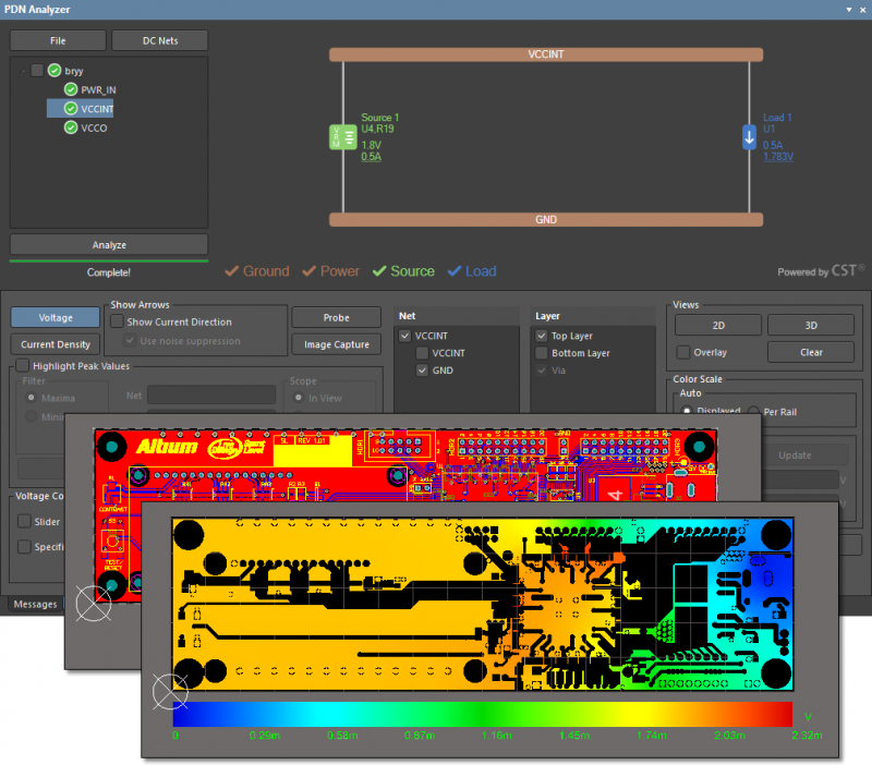
Identify hot spots in your PCB with the PDN Analyzer in Altium Designer.
High Speed and Controlled Impedance Design in Altium Designer
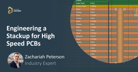
Because PCB stackup design is so important in your next circuit board, you need an intuitive stackup manager with an accurate wideband Debye model for calculating impedance on a copper clad PCB laminate. Altium Designer’s PCB Editor includes the signal, power plane, solder mask, silkscreen, and physical layers necessary to create a real circuit board and prepare for PCB manufacturing. In addition, the PCB Editor allows you to set the dielectric constant and thermal properties of your laminate materials. You can use the Layer Stack Manager to add and remove dielectric layers, select FR4 as a dielectric material, and set the thickness of the FR4 layer.
Unified Design with All FR4 Material Details in Altium Designer
Altium Designer provides you with much more than just an impedance calculator for PCB stackup design. You’ll also have a set of powerful routing tools with an integrated field solver for calculating propagation delay, which is required for accurate trace length matching, impedance matching, and ensuring coupling in differential pairs. The simulation tools help you verify your design, and the documentation features help you plan for PCB manufacturing. You’ll have everything you need to build the highest quality PCBs in Altium Designer.
- Only Altium Designer includes all the design features you need to create schematics, PCB layouts, and manufacturing documentation in a single program.
Learn more about Altium Designer's unified PCB design environment.
- The integrated 3D electromagnetic field solver includes standard models for FR4 dielectric constant, including a model for dispersion and dissipation. You’ll have the features you need for accurate impedance calculations.
Learn more about Simberian’s integrated field solver in Altium Designer.
- You can identify hot spots directly in your PCB layout with a power delivery analysis tool. Altium Designer includes these simulation features as an extension that takes data directly from your PCB layout.
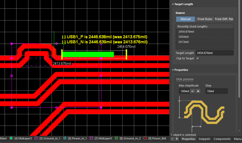
Manage your layers more efficiently with Altium Designer’s Layer Stack Manager.
FR4 laminate material remains the substrate choice for many applications because of its low cost and mechanical properties. Although design teams always seek to minimize cost, Altium Designer’s unified design environment allows teams to design on FR4 or other specialized laminate materials. Designing for advanced high-speed applications is easy in Altium Designer’s unified rules-driven environment.
Altium Designer on Altium 365 delivers an unprecedented amount of integration to the electronics industry until now relegated to the world of software development, allowing designers to work from home and reach unprecedented levels of efficiency.
We have only scratched the surface of what is possible to do with Altium Designer on Altium 365. You can check the product page for a more in-depth feature description or one of the On-Demand Webinars.


