


Flexible Circuits: Enhancing Performance with Shielding, Heat Dissipation, and Stiffeners

At a Glance
Design flex PCBs that perform. Learn where to add shielding, how to dissipate heat, and when stiffeners boost durability and yield in real-world use.


Flex and rigid-flex circuits are often a PCB designers' first choice when they need to save space, shed weight, or eliminate clunky connectors. They've enabled incredible achievements in miniaturized electronics, from medical wearables and drone systems to ruggedized aerospace applications. But as more demanding applications emerge, even the best-designed flex circuits start to show stress.
In many cases, it’s not the routing or signal flow that causes the challenge. It’s EMI, localized heat buildup, and mechanical stress during use often separate a “working” design from one that performs reliably in the field.
Today, we’re looking at three powerful tools that can elevate your flex and rigid-flex designs: EMI shielding, heat dissipation, and mechanical stiffeners. Each one adds some complexity. But when used thoughtfully, they can improve performance, durability, and reliability in meaningful ways.
Key Takeaways
- Flex and rigid-flex circuits increasingly face real-world challenges from EMI, heat buildup, and mechanical stress, even when routing and signal flow look fine on paper.
- EMI shielding (copper hatch, silver ink, or shielding films) can control emissions but adds thickness and stiffness, so it must be carefully placed, grounded, and co-designed with the fabricator.
- Effective thermal management in flex/rigid-flex relies on stackup planning and tools like heat vias, TIMs, and aluminum-backed stiffeners to move heat away from dense component areas.
- Mechanical stiffeners (FR4, polyimide, or metal) are key to reliability and manufacturability, reinforcing areas with components/connectors and improving assembly handling without compromising bend regions.
Shielding
Shielding is typically used when a design is at risk of an emissions problem, something which can occur in flex designs without solid ground planes. Adding shielding to specific regions of the design helps suppress excessive emissions from these regions.
There are several different shielding methods possible for flex circuits:
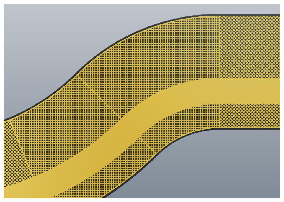
- Cross-hatched copper layers can be placed in the flex stackup as a shielding. Larger hatch openings will reduce shielding effectiveness, but will ensure higher flexibility, and vice versa.
- Silver ink shielding is screen-printed onto the surface. It is more flexible and lightweight but has a slightly lower conductivity.
- Shielding films are pre-formed absorber materials with embedded metal particles and an adhesive backing. A film can be applied directly to the flex circuit surface and they can be an effective option in space-restricted designs.
Note that shielding is not the only solution to emissions, and it is better to focus on locating the root cause of the emissions problem and attempting to solve it first.
However, shielding still has its advantages, and which shielding method is used will depend on the intended electrical performance and mechanical requirements of the application. Whichever technique you choose, it is essential that you ground the shield efficiently and that there be uniform integration in the design.
Also remember that shielding adds stiffness and thickness, which can prohibit bending range and radius. This is one reason it is best to apply shielding near the components that need it because areas near solder joints cannot be bent or flexed anyways. Make sure to model these effects early and work closely with your fabricator to avoid surprises at build or assembly.
Managing Heat
Thermal performance was formerly only a concern in power electronics. Not anymore. As component density increases and enclosures shrink, even low-power flex circuits might end up with heat management issues to solve. Particularly so in rigid-flex boards where active components are bunched together on rigid pieces but the heat is spread out over the whole assembly.
Designers have a number of tools at their disposal to manage heat effectively:
- Heat vias help in moving heat away from critical components to internal copper planes or external thermal structures.
- Thermal interface materials (TIMs) transfer heat from components to heat sinks or enclosure walls.
- Aluminum-backed stiffeners, which we’ll discuss in more detail later, can add structure and also function as passive heat sinks.
In flex designs, thermal management is often tricky. Materials like polyimide and thin adhesives are thermally stable, but they don’t conduct heat well. Even though they can withstand high temperatures, they don’t help much in dissipating heat from components.
This is why it's so important to have correct stackup planning. Thicker copper, relocated elements, or passive heat spreaders may help mitigate hot spots. Make sure to communicate your thermal requirements to your fabricator during the design phase, as material thickness and lamination cycles will affect heat performance.
Stiffeners
Of all the improvements you can make to a flex or rigid-flex circuit, stiffeners are most often overlooked. However, they can have a significant impact on performance, especially during assembly and in-field use.
Stiffeners are used to reinforce mechanically areas in need of it. These are the areas where:
- Components will be mounted, e.g., BGAs or QFNs
- ZIF connectors or press-fit contacts will be mated
- Board will be subjected to pick-and-place or reflow processes
- Flexing should be avoided on handling or installation
Some familiar materials are used for stiffeners:
- FR4 is ubiquitous and possesses good mechanical compatibility with hard sections.
- Polyimide stiffeners are less heavy and may have higher flex but will still contribute stiffness.
- Metal stiffeners like aluminum or stainless steel are rich in strength and can also help with cooling.
Stiffener placement is important. Avoid placing stiffeners in bend areas, and place stiffeners so that they will line up with soldermask or coverlay openings if adhesives are used. You can also vary stiffener thickness in different areas of the design to provide the right combination of flexibility and strength.
Including stiffeners boosts your assembly options. For example, a stiffened flex area would be ideal to use with vacuum pick-and-place whereas an unstiffened one would curl up as it is being placed.
Pulling It All Together
Shielding, thermal management, and mechanical stiffeners are often the distinction between a design that meets specs on paper and one which actually performs in the real world. They are not an afterthought. They are design considerations that ensure long-term performance and reliability.
When designing a flex or rigid-flex design, take a little time to ask yourself a few more questions:
- Will this circuit experience high EMI or high edge rates?
- Are there heat concerns from the size of the enclosure or weight of components?
- Is it easy to build and long-lasting for a lifetime?
The answers to these inquiries can direct you towards one or more of these improvements.
Whether you need to build reliable power electronics or advanced digital systems, Altium Develop unites every discipline into one collaborative force. Free from silos. Free from limits. It’s where engineers, designers, and innovators work as one to co-create without constraints. Experience Altium Develop today!
About Author
Related Resources
Related Technical Documentation
Table of Contents
Design to Release, Without the Friction
- Keep reviews tied to the right version
- Reduce handoff confusion and rework
- Spot sourcing and release risk earlier
- Work solo, share when needed
Get Started
Thank you, you are now subscribed to updates.