



Flexible Soldermask or Polyimide Coverlay, The Pros and Cons

At a Glance
Compare flexible solder mask and polyimide coverlay for flex PCBs. Learn when each fits, how bend radius and copper weight matter, and what drives cost.


When designing flexible circuits, one of the key decisions revolves around the encapsulation and protection of the external circuit layers. Both flexible solder mask and polyimide coverlay serve this purpose, much like the rigid solder masks used for traditional PCB designs. However, flexible circuits face unique challenges due to the constant bending, folding, and dynamic movement they experience during both assembly and end use. This is where selecting the right protective material becomes crucial.
Key Takeaways
- Flexible solder mask is the low-cost option for simple designs. It suits low-layer-count flex circuits with under 2 oz copper and minimal bending, but it can crack under excessive flexing.
- Polyimide coverlay is the industry standard for demanding flex. Choose it for dynamic flexing, tight bend radii, or heavier copper, accepting a higher material and processing cost.
- Coverlay thickness and openings drive both performance and cost. The standard is 1 mil polyimide with 1 mil adhesive, and a good rule of thumb is 1 mil of adhesive per ounce of copper. Drilling, punching, and laser cutting offer increasing precision at increasing cost.
- Involve your fabricator early. Deviating from standard thicknesses can add cost and lead time, so designing around materials the fabricator stocks keeps both in check.
Flexible Solder Mask: A Cost-Effective Option with Limitations
Flexible solder mask closely resembles the standard solder mask used for rigid PCBs, but it is formulated with additives that allow for some degree of flexing and bending. It is applied similarly to rigid board solder mask, making it a more economical option compared to polyimide coverlay, particularly in low-layer-count applications. Additionally, flexible solder mask provides the benefit of tight feature definition, making it an attractive option for designs that require precision.
However, while flexible solder mask is capable of some flexibility, it is important to recognize its limitations. It is not as robust as polyimide film-based solutions, and over time, or under excessive flexing, it can crack. For this reason, flexible solder mask is typically recommended for applications where the circuit will experience minimal bending or flexing, such as in single or double-sided flex circuits with less than 2 oz of copper.
Key Considerations for Flexible Solder Mask
- Ideal for low-cost, low-layer count designs.
- Suitable for circuits that won’t experience significant dynamic flexing or tight bending.
- Can handle designs with less than 2 oz copper.
Polyimide Coverlay: The Go-To for Dynamic Flex and Complex Applications
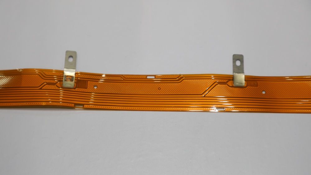
For designs that involve dynamic flexing or require a tight bend radius, polyimide coverlay is the most recommended solution. It is considered the industry standard for flexible circuits due to its superior durability, flexibility, and robustness.
Polyimide coverlay consists of a polyimide film layer combined with an adhesive layer, both available in various thicknesses to suit different applications. Standard options include 1 mil of polyimide with 1 mil of adhesive, but this can be customized depending on the copper thickness or the bend radius requirements. A general rule of thumb is to use 1 mil of adhesive for every ounce of copper to ensure proper encapsulation. Thinner polyimide films may be required for tighter bend radii, while thicker films are necessary for circuits with thicker copper layers.
Film Thickness Options
- Adhesive: ½ mil to 3 mils
- Polyimide Film: ½ mil to 5 mils
Working closely with your fabricator during the design phase is essential when deviating from standard thicknesses, as these customizations can add cost and extend lead times.
The Fabrication Process
Polyimide coverlay does involve a more complex manufacturing process than flexible solder mask, contributing to its higher cost. The polyimide material is typically supplied in roll form, which must be cut to size. Openings for features such as pads and vias can be created using various methods, including drilling, routing, punching, or laser cutting. Afterward, the coverlay is aligned with the circuit and laminated using heat and pressure to bond the adhesive.
Each method of creating openings has specific implications for design:
- Drilling: The most common method but requires careful design to accommodate the round holes created by the drill bits. Larger annular rings may be necessary to account for adhesive squeeze-out during lamination, and designers must be cautious of the "Swiss cheese effect," where too many holes can make the coverlay unstable.
- Punching: More accurate than mechanical drilling, this method allows for tighter tolerances, especially for designs with complex patterns.
- Laser Cutting: The most precise option, laser cutting can accommodate very fine feature sizes and tight tolerances, but it is also the most expensive. It can be done before or after lamination, depending on the design.
When to Deviate from Standard Options
While 1 mil polyimide with 1 mil adhesive is the most cost-effective and commonly used configuration, there are instances when deviating from this standard is necessary. For example, if your design involves dynamic flexing or multiple layers, you may require a thinner coverlay to allow for tighter bend radii. On the other hand, circuits with thicker copper might need a thicker adhesive to ensure proper encapsulation and durability.
Working directly with your fabricator can help balance material availability, cost, and performance needs. Many fabricators maintain stock of standard materials, and designing with these in mind can help keep both costs and lead times manageable.
Balancing Costs: Flexible Solder Mask vs. Polyimide Coverlay
The cost difference between flexible solder mask and polyimide coverlay goes beyond the price of raw materials. While flexible solder mask offers a lower upfront cost, its limitations in terms of flexibility and durability make it a less reliable option for demanding applications. Polyimide coverlay, though more expensive due to its material and processing costs, provides superior protection and flexibility, especially in dynamic and high-stress environments.
Flexible Solder Mask | Polyimide Coverlay | |
Material and processing costs | Lower | Higher |
Best suited for | Simpler, less demanding designs | Circuits requiring dynamic flexing, tight bend radii, or thick copper layers |
Cost-Effectiveness of Flexible Solder Mask vs Polyimide Coverlay
The choice between flexible solder mask and polyimide coverlay ultimately depends on your design’s requirements:
- Use flexible solder mask if your circuit is a low-layer count design with less than 2 oz copper, and if it won’t be subjected to tight bends or dynamic flexing. It’s a cost-effective option for simpler applications where flexibility is required, but not to an extreme degree.
- Choose polyimide coverlay if your design involves dynamic movement, tight bend radii, or heavier copper layers. While more expensive, polyimide coverlay offers unmatched durability, flexibility, and reliability in demanding environments.
When in doubt, consider consulting with your fabricator early in the design phase to identify the most suitable material for your specific application.
Frequently Asked Questions
What is the difference between flexible solder mask and polyimide coverlay?
Flexible solder mask is a rigid-board-style solder mask formulated with additives that allow limited bending. Polyimide coverlay is a polyimide film bonded with an adhesive layer, which makes it more durable and flexible. Solder mask costs less and gives tighter feature definition, while coverlay is the industry standard for flex circuits.
When should I use polyimide coverlay instead of flexible solder mask?
Use polyimide coverlay for dynamic flexing, tight bend radii, or heavier copper. Flexible solder mask suits low-layer-count designs with less than 2 oz of copper and minimal bending, because it can crack over time under excessive flexing. Coverlay costs more in material and processing but is more reliable in demanding applications.
What coverlay thickness should I specify for a flex PCB?
The standard and most cost-effective option is 1 mil of polyimide with 1 mil of adhesive. A common rule of thumb is 1 mil of adhesive for every ounce of copper, so thicker copper needs thicker adhesive for proper encapsulation. Tighter bend radii call for thinner polyimide film. Confirm any non-standard thickness with your fabricator first, since it can add cost and lead time.
How are coverlay openings made, and which method suits fine features?
Coverlay openings for pads and vias are made by drilling, routing, punching, or laser cutting. Drilling is the most common but needs larger annular rings to allow for adhesive squeeze-out, and too many holes can cause the “Swiss cheese effect.” Punching gives tighter tolerances, and laser cutting is the most precise but also the most expensive. For the finest features, flexible solder mask offers tighter definition than coverlay.

About Author
Related Resources
Related Technical Documentation
Table of Contents
Solutions for Every Role and Team
- Discover and evaluate design options earlier
- Develop in one shared workspace
- Scale with control and compliance
- Connect every stage of hardware development
Learn More
Thank you, you are now subscribed to updates.