
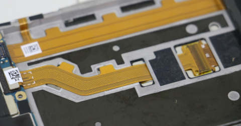
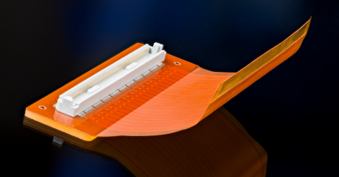




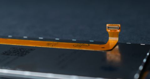




Copper Weight in Rigid-Flex: Why One Spec Doesn't Work Across the Board

At a Glance
Learn why a single copper weight spec fails in rigid-flex designs. Discover zone-specific guidelines for rigid, flex, and transition areas.


Several years back we had a rigid-flex come through that had gone through multiple design reviews before it ever hit the floor. Good team, thorough process, nothing obviously wrong. When the boards came back, the flex area wouldn't bend. At all. It was rigid through the entire zone that was supposed to flex. Too many layers laminated together across too short a span.
The respin unbonded those layers in the flex zone so they could move independently. That one change made the difference between a board that worked and one that didn't.
That project comes to mind whenever a rigid-flex design comes in with a single copper weight called out across the entire board. It's not always wrong, to be clear. But it's a flag worth another look, because copper weight in a rigid-flex isn't really one decision, it's several, and they interact with the stack-up in ways that don't show up until something doesn't move the way it's supposed to.
Key Takeaways
- Copper weight in rigid-flex is zone-specific. What works in the rigid section can create real problems in the flex zone.
- The transition area between rigid and flex has its own set of considerations.
- Rolled annealed copper behaves differently than electrodeposited copper in flex applications, and that difference matters when bend life is a requirement.
- The stack-up and the copper spec need to be developed together, not one after the other.
The Rigid Zone
In the rigid sections of a rigid-flex, copper weight decisions look a lot like standard PCB practice. One ounce is a common starting point. Two ounces shows up when current carrying capacity or impedance requirements push that direction. Design rules, via structures, plating considerations are similar. Most of this is familiar ground for anyone who's designed rigid boards before.
Here's the catch. The copper weight you choose in the rigid zone affects what's achievable in the flex zone, because they're part of the same laminate system. If the outer layer copper in the rigid section is heavy, that same copper is carried into the flex zone whether anyone planned for it or not. It is not automatically a problem, but should be thought through.

The Flex Zone
This is the zone where copper weight decisions have the most direct impact on whether the board performs the way it's supposed to.
Heavier copper means a stiffer circuit. Sounds obvious, but the practical implications don't always get accounted for at layout. Half ounce copper is common in flex zones for exactly this reason. It bends more readily, distributes stress more evenly across the cross-section, and holds up better over repeated flex cycles than heavier copper does. One ounce in a dynamic flex application is worth a conversation with your fabricator before the design goes out. Two ounces is rarely the right call in a flex zone unless bend requirements are essentially static and current capacity leaves no other option.
Copper foil type matters too, and it's one of the more underspecified things on fabrication drawings that I see. Electrodeposited copper is the default in most rigid fabrication, and it's fine in rigid zones. In flex zones that will see repeated bending though, rolled annealed copper is the better choice. The grain structure runs in a direction that handles flex stress noticeably better than ED copper. If bend life matters for your application and RA copper isn't called out in the flex zone, that's worth thinking through.
Trace geometry interacts with copper weight in ways that are easy to miss too. Thinner copper allows narrower traces at a given impedance target, which means less copper mass moving with the circuit. Running traces perpendicular to the bend axis, curved routing instead of right angles, balanced copper distribution across the cross-section. All standard flex practice, and all of it works better with the right copper weight underneath.
The Transition Zone
The area where rigid meets flex is where a lot of rigid-flex problems actually start, and copper weight plays a role in why. By definition, the transition zone sees stress concentration. The circuit goes from a constrained, supported structure to a flexible one, and the mechanical behavior changes abruptly right at that boundary. Heavy copper through the transition makes that abruptness worse. It creates a stiffer point that resists the flex zone doing what it needs to do, and that's exactly what happened on the board I mentioned earlier. The layers were bonded together through the transition and into the flex zone. The copper weight added to the stiffness. The result was a circuit that physically could not bend.
A few things help here. Keep copper weight as consistent as possible between the rigid and flex zones rather than stepping it up right at the rigid section edge. Avoid running high copper weight planes all the way to the edge of the rigid area. And if the design allows it, give the transition zone a little more physical length than seems necessary. Stress distribution improves with distance, more than people expect.
Talking to Your Fabricator Before the Stack-Up Is Final
This is one of those decisions that's a lot easier to get right before the stack-up is locked than after. Once layer count, laminate materials, and copper weights are set, changing any of them ripples into thickness, impedance, and sometimes which fabricators can even build the board.
Worth asking early: what copper foil type is standard in their flex builds, and what does specifying RA copper do to lead time or cost? What copper weight do they see most often for your bend requirement, and where have they run into trouble? If there's a transition zone concern, how have they handled it on similar designs?
Fabricators who build rigid-flex regularly have seen what these decisions do downstream in ways that are hard to replicate in a design review. Ask the questions.

Before You Release the Design
A few things worth checking before the design goes out to fabrication.
- Is there a single copper weight called out across the whole board, or have the rigid zone, flex zone, and transition area actually been considered separately?
- Is copper foil type specified in the flex zone, or left to the fabricator default?
- For a dynamic flex application, is half ounce RA copper either specified or explicitly ruled out?
- Has the stack-up been reviewed with the fabricator before release, not after the first articles land?
The board that couldn't bend taught me that a design can pass every review and still not work, if the stack-up and the copper spec weren't developed as one system. The flex zone has to actually be able to flex.
Ready to move your rigid-flex design from layout to release with less friction? Altium Develop gives individual engineers and small teams Altium-grade design capability with simple ways to share work, collect feedback, and stay in sync without the overhead.
Get started with Altium Develop →
Frequently Asked Questions
What copper weight should I use in the flex zone of a rigid-flex design?
Half ounce (0.5 oz) is the most common starting point for flex zones. It bends more readily, distributes stress more evenly, and holds up better over repeated flex cycles than heavier copper. One ounce is workable in static applications but warrants a conversation with your fabricator before committing. Two ounces is rarely appropriate in a flex zone unless bend requirements are essentially static and current capacity leaves no other option.
What is the difference between rolled annealed (RA) and electrodeposited (ED) copper in flex applications?
Electrodeposited copper is the standard in rigid PCB fabrication and performs well in rigid zones. Rolled annealed copper has a grain structure that runs in a direction better suited to handling the stress of repeated bending, making it the preferred choice in flex zones where bend life is a requirement. If RA copper is not explicitly called out on the fabrication drawing, most fabricators will default to ED so it is worth specifying.
Does copper weight in the rigid zone affect the flex zone?
Yes. Because rigid and flex zones are part of the same laminate system, heavy outer layer copper in the rigid section carries into the flex zone whether it was planned for or not. This doesn't automatically cause problems, but it needs to be accounted for during stack-up development, not discovered after fabrication.
When should I involve my fabricator in copper weight decisions for a rigid-flex design?
Before the stack-up is finalized. Once layer count, laminate materials, and copper weights are locked, changing any of them ripples into thickness, impedance, and potentially which fabricators can build the board at all. Fabricators who regularly build rigid-flex have seen how these decisions play out downstream, involving them early is one of the most reliable ways to avoid a costly respin.

About Author
Related Resources
Related Technical Documentation
Table of Contents
- Key Takeaways
- The Rigid Zone
- The Flex Zone
- The Transition Zone
- Talking to Your Fabricator Before the Stack-Up Is Final
- Before You Release the Design
- Frequently Asked Questions
- What copper weight should I use in the flex zone of a rigid-flex design?
- What is the difference between rolled annealed (RA) and electrodeposited (ED) copper in flex applications?
- Does copper weight in the rigid zone affect the flex zone?
- When should I involve my fabricator in copper weight decisions for a rigid-flex design?
Design to Release, Without the Friction
- Keep reviews tied to the right version
- Reduce handoff confusion and rework
- Spot sourcing and release risk earlier
- Work solo, share when needed
Get Started
Thank you, you are now subscribed to updates.