




Flex Material Realities: Why You Can't Always Get the Dielectric Thickness You Want

At a Glance
Learn why flex circuit dielectric thickness can't always match your spec. Understand polyimide limits, adhesive variability, and how to design for what's real.


When I speak with first-time flexible circuit designers, there is one theme that resonates over and over again: the stack-up. It's all too easy to fall into the habit of specifying dielectric thicknesses to the decimal point, particularly when pursuing impedance goals or attempting to navigate a rigid-flex transition. But the fact is this: unlike rigid laminates, flexible materials aren't listed in an infinite number of thicknesses. Choices are restricted, availability is more limited, and frequently your design need is better met by letting flexibility lie in your fabricator's hands rather than dictating values.
In this article, I want to pull back the curtain and reveal to you what really happens with flex materials and why it's so important that designers are aware of the limitations. By the end of this, you'll know how knowing "what's real" can help you create more manufacturable stack-ups and avoid project delays.
Key Takeaways
- Flexible materials come in fixed, limited thicknesses. Unlike rigid laminates, polyimide is manufactured in standard increments (typically 12 µm, 25 µm, and 50 µm). Designing to precise custom thicknesses that don't exist in production will stall a project or force a redesign.
- Adhesive layers add uncontrolled thickness to the stack-up. Adhesive-based laminates introduce an additional dielectric layer whose final thickness varies with resin flow and press conditions. This variability directly affects impedance calculations and cannot be treated as a fixed value.
- Coverlays and stiffeners behave differently than their rigid-board equivalents. Coverlays are substantially thicker than soldermask and introduce adhesive flow variability. Stiffeners are standard FR4 prepreg; useful for mechanical reinforcement, but not a precision dielectric element.
- Specify electrical requirements, not exact dimensions. The most reliable approach is to define impedance targets and mechanical needs, then let the fabricator select materials from available stock. Chasing a precise dielectric number that doesn't exist in supply leads to delays, cost overruns, or a stack-up that doesn't perform as intended.
The Designer's Perspective
From the designer's point of view, dielectric thickness is all about control. You want tight impedance for high-speed signals. You want to have uniform spacing for differential pairs. You want the stack-up to balance at the rigid-flex junction. And the CAD tools make it so easy to say exactly what you want.
If your field solver tells you that you need 1.87 mils of copper layer spacing to get 50 ohms, why wouldn't you key that right into your drawings? The problem is, flex material does not do your bidding - pun intended. The "optimal" thickness that you design for may not be offered by your supplier, and if it is offered, it may not be in stock or on the shelf.
The Fabricator's Reality
Let's take a closer look at what fabricators have to work with regarding flex materials.
Polyimide
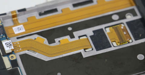
Polyimide is the workhorse of flexible circuits in the industrial world. It's manufactured in standard thicknesses: typical values are 12 µm, 25 µm, and 50 µm (about 0.5, 1, and 2 mil). Designers are required to conform to these material thickness values when calculating nominal impedance/trace width and bending radii.
Adhesives vs. Adhesiveless Laminates
The choice between adhesive-based and adhesiveless laminates is a fundamental decision that dictates both the final performance and the manufacturing complexity of a flexible circuit. While both methods serve to bond copper to the polyimide base, the presence or absence of an additional "glue" layer significantly impacts the stack-up's electrical characteristics, thermal stability, and overall thickness.
- Adhesiveless laminates bond copper directly to polyimide. Thin, flexible, and superior electrical performance.
- Adhesive-based laminates add an extra "glue" layer between copper and film, which changes dielectric constant and thickness.
- After lamination, actual thickness is dependent on resin flow, copper weight, and press conditions, not a guaranteed "fixed" value.
Coverlays vs. Soldermask
We think of soldermask as a thin protective coating in rigid boards. In flex, we use coverlays, effectively pieces of polyimide with adhesive. Coverlays are much thicker than soldermask and provide variability due to adhesive flow. They are needed for protection and flexibility but you can't adjust them like a layer of soldermask.
Stiffeners
A stiffener is not a “special” type of rigid material, it is standard FR4 prepreg that can be bonded to a flex ribbon. The role of a stiffener is to add strength to specific regions of the flex PCB, especially for assembling connectors, mechanical elements, or higher-pin count components. Since these are commercially available materials, there is a range of thicknesses available to reach a specific mechanical thickness.
Supply Chain and Stocking Problems
Just because a material supplier posts a wide range of thicknesses, it does not necessarily mean your fabricator stocks them. Flex materials are specialty items. Some advanced films, like liquid crystal polymer (LCP) or high-reliability polyimides, may have lead times up to several months.
If your stack-up has to be a non-standard thickness, your project can freeze for material, or the fab house will have to suggest a replacement. Either way, there is delay, cost, or redesign. The only way to prevent this is to work with thicknesses that are standard stock and call out electrical requirements rather than absolute size.
When material limitation and design intention collide, provide. If you're bent on having a thickness of dielectric that doesn't exist, the fabricator will either argue with your spec or produce something that won't work to your goals.
A Practical Example
Your impedance calculator tells you that 50 ohm single-ended lines take 1.8 mils of dielectric material. You put "1.8 mil" into the stack-up and head for your fab house. Problem: polyimide film is available in 1 mil or 2 mil. In addition, the stackup requires adhesives for certain copper films or multi-layer stacks, so that thickness (typically 1 mil) must be included as part of any calculation.
The result is that the actual dielectric thickness is 3 or 4 mil for a central core layer, or 1-2 mil on an outer layer. Either can be utilized to meet an impedance requirement, depending on linewidth and copper weight. The fab will recommend the optimal solution for electrical performance vs. manufacturability.
Conclusion
Designing with flexible materials is different from designing with hard laminates. By specifying what you need electrically and mechanically, and by letting your fabricator drive the selection of materials, you won’t start pursuing thickness numbers that are unrealistic or non-existent.
The next time you're specifying a flex or rigid-flex stack-up, take your fingers off the keyboard before typing in that highly precise dielectric number. Instead, ask yourself: "What do I have on hand, and how can I meet my design needs with what I have?" That conversation can make all the difference between a smooth, on-time build and a project stuck in material purgatory.
Altium Develop provides a purpose-built environment for flex and rigid-flex circuit design, with integrated stackup management, design rule checks, and cross-disciplinary collaboration tools that help you align electrical requirements with real-world material constraints before you reach the fab house. Get started with Altium Develop →
Frequently Asked Questions
What dielectric thicknesses are available for flex circuits?
Polyimide, the standard dielectric for flex circuits, is manufactured in fixed increments, typically 12 µm (0.5 mil), 25 µm (1 mil), and 50 µm (2 mil). These are the values designers must work within. Specifying anything outside these standard thicknesses risks material unavailability, fabrication delays, or a stack-up that cannot be built as drawn.
Why can't I just specify the exact dielectric thickness my impedance calculator requires?
Flex materials don't ship in arbitrary thicknesses the way rigid laminates do. If your field solver returns 1.8 mil, that value doesn't exist in production polyimide film. The correct approach is to define your impedance target and let your fabricator select the nearest available material combination, adjusting trace width and copper weight to hit the electrical requirement with real stock materials.
Does an adhesive layer affect my stack-up thickness and impedance?
Yes, significantly. Adhesive-based laminates add a bonding layer (typically around 1 mil) between the copper and polyimide, and its final thickness varies with resin flow and press conditions. This variability shifts your effective dielectric thickness and must be factored into impedance calculations. Adhesiveless laminates eliminate this layer, giving tighter thickness control and better electrical predictability, at a cost premium.
What is a coverlay and how does it differ from soldermask?
A coverlay is the flex circuit equivalent of soldermask, but it is a laminated polyimide film with adhesive rather than a thin coating. It is substantially thicker than soldermask, and its final thickness varies with adhesive flow during lamination. Unlike soldermask, it cannot be precisely tuned after the fact; its contribution to the overall stack-up must be accounted for in the design before fabrication begins.

About Author
Related Resources
Related Technical Documentation
Table of Contents
Design to Release, Without the Friction
- Keep reviews tied to the right version
- Reduce handoff confusion and rework
- Spot sourcing and release risk earlier
- Work solo, share when needed
Get Started
Thank you, you are now subscribed to updates.