








What to Include in a Rigid-Flex Design Review

At a Glance
Learn what belongs on a rigid-flex design review checklist. Cover stackups, transition zones, bend requirements, and fab notes before issues get expensive.


Rigid-flex technology gives the designer unprecedented freedom in connecting multiple circuit zones without bulky connectors or cables, creating smaller, lighter assemblies that can meet the mechanical demands of the operating environment. But as anyone who's spent time working on rigid flex designs will know, rigid-flex designs come with their own unique set of challenges. The transition zones, material choices, and mechanical constraints can make or break both manufacturability and long-term reliability.
That's why a well-structured design review is so important. Let's take a practical look at what belongs on your rigid-flex design review checklist and how catching issues early can save both time and money later in the process.
Key Takeaways
- Confirm your stackup with the fabricator before layout begins, not after. A short conversation at this stage can prevent material delays and process mismatches that are expensive to fix later.
- The rigid-to-flex transition zone is the most failure-prone area of any rigid-flex design. Coverlay pull-backs, copper alignment, and stiffener placement all need explicit attention during review.
- Bend radius, trace orientation, and via placement in flex areas are structural decisions. Getting them wrong leads to copper fatigue, cracking, and failures that often don't appear until the product is in the field.
- Your master drawings are the voice of your design once it leaves your desk. Inconsistent layer names, missing callouts, or copied fab notes are among the most common and most avoidable sources of production delay.
Begin With the Big Picture
Before you begin working with stackups and coverlays, go through the exercise of getting everyone to agree on the intent of this design. What is this circuit supposed to do, and how will it live in the real world?
Success with rigid-flex often comes down to understanding how and when the flex portions will move. Is this a dynamic flex that bends hundreds of times during use, or a static flex that's folded once during assembly and left in place? Those two situations demand completely different material choices and layout strategies.
It's also good to talk through environmental factors like temperature ranges, vibration, moisture exposure, and any unique mechanical constraints of the enclosure. When the team understands how the finished product will function, every design decision becomes more intentional.
Stackup and Materials Review
If you remember only one thing from this article, let it be this: confirm your stackup early and confirm it again before layout begins.
Rigid-flex stackups aren't just variants of a regular FR-4 design. They contain multiple material systems, adhesives, copper weights, and dielectric thicknesses that interact in ways you can't always predict without experience or simulation. Adhesiveless flex cores behave differently than adhesive-based ones. Copper weights that look fine on a rigid layer might be far too stiff for a flex region.
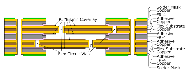
Ask your fabricator to review your proposed stackup before you lock it in. They can confirm material availability, controlled impedance tolerances, and whether your planned transitions are realistic for their process. A short conversation at this stage can prevent a delay later when you discover that one of your specialty flex cores is on a 12-week lead time.
Pay Attention to the Transition Zones
As a general rule, the rigid-to-flex transition is the most sensitive and failure-prone area of a rigid-flex design, so give it extra attention during review. First, ensure that copper features in both the rigid and flex areas are properly aligned and spaced adequately from the transition edge. Check coverlay pull-backs and reliefs; these details prevent cracking and delamination of the board when bent. Note the image below, which shows the stifferener, integrated rigid, and flex regions in the design.
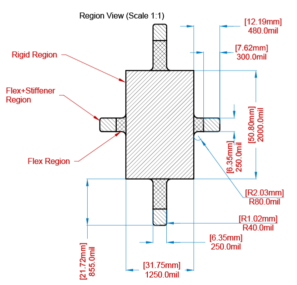
Mechanical stiffener outlines, mechanical cutouts, and fillet shapes should be well-defined in your mechanical layers. However, it is easy to forget to take into account how the adhesive layers and coverlay thicknesses add up to the total height at the interface when accounting for mechanical fit.
Review Bend Requirements and Dynamic Flex Areas
Next, pay close attention to how the board will bend: bend radius, direction, and number of cycles make a difference. In dynamic flex regions, the traces should run perpendicular to the bend axis when possible for dynamic flex regions, and they need to be staggered from one another to distribute strain. Vias in bend areas should be avoided. They become stress concentrators that can crack during repeated movement.
If you’re working on a tight bend, review your copper thickness and dielectric stack carefully. Thinner copper and adhesiveless constructions are more flexible but do require special consideration in manufacturing.
Here’s where a low-tech solution can help: print your design at 1:1 scale on paper, cut it out, and fold it like the final product. It’s a fast way to visualize whether bends, clearances, and stiffener placements make sense before you send anything to fab. A little time with scissors and tape can save thousands of dollars in rework.
Fabrication and Assembly Considerations
Rigid-flex designs don't behave like standard boards on the production floor, so bring your fabricator and assembler into the discussion early.
Confirm panelization and array design. These may look very different from regular FR-4 panels due to the need for flex support during handling. Discuss coverlay openings, solder mask transitions, and where components can safely be placed near flex zones.
Check the drill charts and via requirements. For example, a plated-through via passing through both rigid and flex sections requires very careful control of plating and thermal exposure. Also, double-check the way the stiffeners are to be bonded and if reflow heat could affect adhesive performance.
I've witnessed more than one design be delayed because a stiffener overlapped a bend area, or was placed too close to a connector, and caused warpage during assembly. These details seem small until they aren't.
Don't Forget Master Drawings
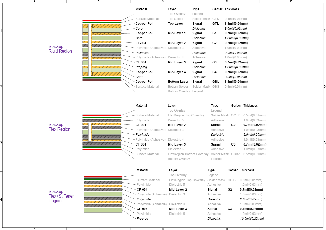
Your fabrication drawing and your notes are the voice of your design once it leaves your desk. If they're unclear, even the best layout can stumble. Include clear stackup diagrams, layer designations, and callouts for all special features, including bend areas, stiffeners, coverlays, adhesives and flex material types. Ensure that your drill charts, impedance requirements, and controlled dielectric notes reflect the CAD data exactly.
If your layer names are different between the design file, drawing, and Gerbers, you're asking for confusion. Master drawings should clearly delineate between different regions in the stackup, which may contain stiffeners, such as in the stackup drawing shown below. In Altium Draftsman, layer names can be assigned to their Gerber layer extensions, as shown below.
Bring in Your Fabricator Early
This cannot be emphasized enough: include your fabricator in the design review before you hit "release to manufacturing." They've seen dozens, if not hundreds, of rigid-flex designs and can spot pitfalls in minutes that may take you weeks to uncover on your own. They'll also know which material combinations are proven in production and which may require extra validation. A collaborative review doesn't just improve yield; it shortens the learning curve for your next design. Think of your fabricator as an extension of your design team, not just the final step in the process.
Wrapping It Up
From high-performance wearables to new advanced aerospace systems, rigid-flex circuits open up incredible design possibilities. But the same flexibility that makes them appealing also makes them complex. A structured design review, including intent, materials, transitions, bending, fabrication, and documentation gives you the best shot at success. What really matters is the real-world impact: fewer revisions, smoother assembly, and a design you can trust to perform.
Rigid-flex designs demand more from your tools and your process than standard PCB work. The review habits covered in this article all depend on having a workflow where your design data, outputs, and decisions stay connected from start to finish.
Altium's electronics design platform is built to support that workflow, whether you're an individual designer working through complex builds on your own or a team coordinating across disciplines and stakeholders. Explore how Altium can help you design, review, and release with more confidence and fewer surprises.
Frequently Asked Questions
What is the difference between static and dynamic flex, and why does it matter for design review?
Static flex is bent once during assembly and stays in position. Dynamic flex bends repeatedly during normal product use. The distinction drives nearly every material and layout decision in the review: copper weight, bend radius, trace orientation, and stackup construction all change depending on which type you're designing. Reviewing a dynamic flex design against static assumptions is one of the most common sources of field failures.
Where should vias be avoided in a rigid-flex design?
Vias should not be placed in bend areas or within the rigid-to-flex transition zone. In bend areas, vias become stress concentrators that crack during repeated flexing. In transition zones, the mechanical stress from bending can cause barrel cracks in plated-through holes over time. As a general rule, keep plated-through holes at least 20 mil from any bend area and keep vias well clear of the transition boundary.
What should a rigid-flex fabrication drawing include that a standard PCB drawing doesn't?
A rigid-flex fab drawing needs explicit callouts for transition zone boundaries, bend area designations, coverlay pull-back dimensions, stiffener placement and bonding method, and flex material types with adhesive thicknesses. Layer names must be consistent across the design file, Gerbers, and the drawing itself. Anything the CAD tool doesn't define automatically, particularly transition zone location and size, must be captured in the notes, clearly and specifically.
How do you verify a rigid-flex design will fold correctly before sending files to fabrication?
Print the board outline at 1:1 scale, cut it out, and fold it to match the final assembly. This low-cost method quickly reveals whether bend radii, stiffener placements, and clearances are realistic before any files are submitted. For more complex geometries, 3D modeling in ECAD tools with MCAD integration can simulate the folded state and flag mechanical conflicts that are invisible in a flat 2D view.

About Author
Related Resources
Related Technical Documentation
Table of Contents
- Key Takeaways
- Begin With the Big Picture
- Stackup and Materials Review
- Pay Attention to the Transition Zones
- Review Bend Requirements and Dynamic Flex Areas
- Fabrication and Assembly Considerations
- Don't Forget Master Drawings
- Bring in Your Fabricator Early
- Wrapping It Up
- Frequently Asked Questions
- What is the difference between static and dynamic flex, and why does it matter for design review?
- Where should vias be avoided in a rigid-flex design?
- What should a rigid-flex fabrication drawing include that a standard PCB drawing doesn't?
- How do you verify a rigid-flex design will fold correctly before sending files to fabrication?
Solutions for Every Role and Team
- Discover and evaluate design options earlier
- Develop in one shared workspace
- Scale with control and compliance
- Connect every stage of hardware development
Learn More
Thank you, you are now subscribed to updates.