





Rigid-Flex Assembly: What Happens After Fabrication

At a Glance
Learn what rigid-flex designers miss after fabrication. Avoid assembly failures by addressing fixturing, reflow profiles, and component placement before first article.


A lot of what I talk about in these blogs is flex and rigid flex from a fabrication perspective to help PCB designers better understand the real-world challenges and considerations. Not to date myself, but when I first started in the industry, there were so many more fabricators and it was very common for customers to visit fabricators on a very regular basis to learn more about processes and more specifically, where their designs were pushing process parameters and have discussions on how to problem-solve through these challenges.
Today, there are so many less fabricators to visit and, in my opinion, as good as virtual calls can be, they cannot replace that interaction on the shop floor and the ability to understand things in a real-world scenario.
But that is a problem to solve another day.
Past blogs have talked about stack-up decisions, transition zone geometry, copper weight across zones, registration tolerances, etc. Those are the right things to think about, and they get a lot of attention for good reason.
But there's a second set of challenges that starts the moment the board arrives at the assembler, and the design decisions that impact those processes are worth talking about too. Often, designers don't get direct feedback from the assembly floor. The board either passes or it doesn't, and if it doesn't, the failure analysis doesn't always make it back to the layout.
Key Takeaways
- Rigid-flex behaves differently than rigid boards during assembly, and the design choices that affect that behavior are often made at layout.
- Component placement near the flex zone, thermal mass distribution across rigid and flex sections, and the mechanical constraints available to the assembler all influence whether the assembly goes smoothly.
The Assembler Is Working With a Different Animal
A rigid board goes into a fixture, sits flat, runs through reflow, comes out. The process is well understood and the equipment is designed around it.
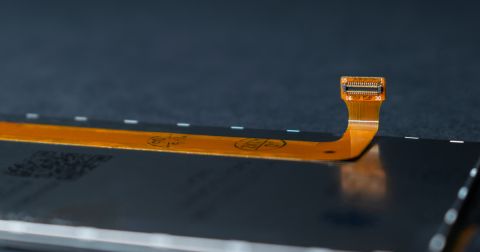
Rigid-flex doesn't always cooperate with that workflow. The flex sections introduce compliance into what should be a flat, stable assembly. Depending on the construction, the board may want to curl or shift during handling, the thermal mass may be uneven, rigid sections heat and cool differently than flex sections, and those differences can affect solder joint quality if the reflow profile isn't adjusted for it.
Assemblers who work with rigid-flex regularly know how to manage this. They have custom fixtures, adjusted profiles, and handling protocols built around the format. Assemblers who see it occasionally may be figuring it out on your board, which is something worth knowing before you start that first assembly run!
Component Placement Near the Flex Zone
This is where design decisions have the most direct impact on assembly outcomes, and it's also one of the things that doesn't always get enough attention during design review.
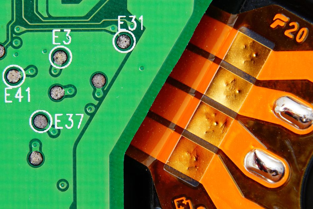
The transition zone between rigid and flex sections is a mechanically active area. It sees stress during handling, stress during fixturing, and stress during the thermal cycling of reflow. Components placed too close to that transition are sitting in a zone that moves, and solder joints in moving zones fatigue faster than solder joints on stable rigid substrate.
The general guidance is to keep components away from the rigid-to-flex transition. How far depends on the specific construction and the application, and your fabricator can give you a number based on the stack-up. Ask!
As a side note, Via-in-pad near the transition zone adds another layer of complexity. Filled and plated vias handle the mechanical stress better than unfilled ones, and in rigid-flex that differentiation matters more than it does on a standard rigid board.
Fixturing: What the Assembler Needs the Design to Support
Custom fixtures for rigid-flex assembly aren't unusual, but they do require something to fixture against. The rigid sections provide that. The flex sections don't.
Designs where the flex zone is large relative to the rigid sections, or where the rigid sections are small and oddly shaped, create fixturing challenges that add cost and complexity at assembly. In some cases, they make consistent reflow difficult regardless of how good the fixture is.
This is something to think about during the mechanical layout phase, not just the electrical layout phase. Some things to consider:
- Where are the rigid sections relative to the components that need to be soldered?
- Is there enough rigid area to support fixturing without putting mechanical load on the flex zone during reflow?
- If the assembly requires a two-sided reflow, which side goes first and what does the board look like when it's flipped?
These are questions an assembler will ask. Having answers before the design is released makes the conversation shorter and the outcome much more predictable.
Thermal Management Across Zones
Reflow profiles are designed around the thermal mass of the board. Rigid-flex complicates that because the thermal mass isn't uniform. Rigid sections with copper planes heat and cool at a different rate than flex sections with minimal copper and the result is that a profile optimized for one zone may not be ideal for the other.
In practice, assemblers adjust for this. But the adjustment is easier when the designer has thought about thermal distribution during layout. Heavy copper pours in rigid sections close to the flex zone create steep thermal gradients at the transition and components on the flex section near that boundary may see temperature profiles that differ from what the datasheet specifies.
This doesn't mean avoiding copper near the transition. Plane management in rigid-flex is a separate topic with its own set of tradeoffs (and probably a future blog topic). It means being aware that the thermal behavior of the board during reflow is influenced by those decisions, and that the assembler is managing that variation downstream.
The Conversation Worth Having Before First Article
The easiest way to avoid assembly surprises on a rigid-flex program is to bring the assembler into the review before the design is released, not after the first articles come back with questions. It wasn’t too long ago that I was with a fabricator and assembler, and the assembler’s comment was: “We just have to figure out how to make things work with what we are given.” How great would it be to have those conversations before the design was released and everyone involved had time to analyze and make recommendations!
Before You Release the Design
A few things worth confirming before the rigid flex design goes out:
- Are components kept a defined distance from the rigid-to-flex transition, and is that distance based on actual stack-up geometry rather than available space?
- Are via-in-pad features near the transition zone specified as filled and plated?
- Has the fixturing strategy been discussed with the assembler, and is there enough rigid area to support it?
- Has the reflow profile been considered in the context of the thermal mass distribution across rigid and flex sections?
The fabrication conversation on rigid-flex is well established. The assembly conversation deserves the same attention.
Rigid-Flex Assembly: Frequently Asked Questions
How far from the rigid-to-flex transition zone should components be placed?
There is no single universal number. The safe keepout distance depends on the specific stack-up construction and the application. A practical starting assumption is 1 mm to 3 mm, but the working figure should be confirmed with your fabricator based on actual stack-up geometry before layout is finalized. Components should always sit on rigid or stiffened sections, never on unsupported flex.
Why does rigid-flex require a different reflow profile than a standard rigid board?
Rigid and flex sections have different thermal masses and heat at different rates. FR-4 rigid sections with copper planes absorb and release heat faster than polyimide flex sections with minimal copper. A single reflow profile optimized for one zone may overstress the other. Assemblers typically use a slower ramp and extended soak zone to allow even heating across both materials and reduce the risk of delamination or solder joint damage near the transition.
What makes rigid-flex assembly fixturing more complex than standard PCB assembly?
Flex sections have no inherent stiffness, so the board cannot simply sit flat in standard fixtures during reflow. Assemblers fixture against the rigid sections. When rigid sections are small, oddly shaped, or poorly positioned relative to the components being soldered, consistent fixturing becomes difficult regardless of fixture quality, adding cost and increasing the risk of inconsistent solder joints across the board.
Should via-in-pad be avoided near the rigid-to-flex transition zone?
Not necessarily avoided, but specified carefully. The transition zone is mechanically active. It sees stress during handling, fixturing, and thermal cycling. Unfilled vias in that area are more vulnerable to that stress than on a standard rigid board. Filled and plated vias handle the mechanical load significantly better, and in rigid-flex designs near the transition zone, that specification matters more than it would elsewhere on the board.

About Author
Related Resources
Related Technical Documentation
Table of Contents
- Key Takeaways
- The Assembler Is Working With a Different Animal
- Component Placement Near the Flex Zone
- Fixturing: What the Assembler Needs the Design to Support
- Thermal Management Across Zones
- The Conversation Worth Having Before First Article
- Before You Release the Design
- Rigid-Flex Assembly: Frequently Asked Questions
- How far from the rigid-to-flex transition zone should components be placed?
- Why does rigid-flex require a different reflow profile than a standard rigid board?
- What makes rigid-flex assembly fixturing more complex than standard PCB assembly?
- Should via-in-pad be avoided near the rigid-to-flex transition zone?
Solutions for Every Role and Team
- Discover and evaluate design options earlier
- Develop in one shared workspace
- Scale with control and compliance
- Connect every stage of hardware development
Learn More
Thank you, you are now subscribed to updates.