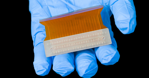

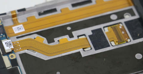
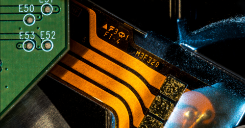
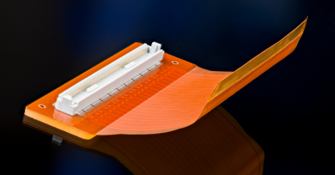





Dynamic Flex vs. Static Flex: Why the Design Rules Are Not Interchangeable

At a Glance
Avoid flex circuit failures. Understand the key design differences between static and dynamic flex: bend radius, copper spec, and trace geometry.


The cracks followed the traces almost perfectly. Not random, not scattered, and under magnification, they ran along the copper geometry like the circuit had mapped its own failure. Fatigue cracks, initiating at trace edges, propagating through the bend zone cycle by cycle until the circuit stopped working somewhere in the field.
A wearable device, six weeks into production returns, and the pattern was telling anyone who knew how to read it exactly what had gone wrong.
The flex circuit had been designed to static rules. In an application that never stopped moving.
That is a hard lesson, and it is more common than most people expect.
If you are new to flex circuit design, one of the most important things to understand early is that flexible circuits are not a single design category. The rules that produce a reliable static flex circuit, one that bends once during assembly and stays in position, are meaningfully different from the rules that govern dynamic flex, which is designed to flex continuously throughout its service life. Applying static rules to a dynamic application is one of the more reliable ways to end up with field failures that are difficult to diagnose and expensive to fix.
Key Takeaways
- Static and dynamic flex circuits are fundamentally different design categories. Static flex bends once during assembly and stays fixed; dynamic flex bends repeatedly. Applying static design rules to a dynamic application is a reliable path to field failures.
- Bend radius is critical in dynamic applications. Tighter isn't better. Dynamic flex demands a minimum bend radius of roughly 10× the circuit thickness (vs. 6× for static) to avoid copper fatigue and cracking under repeated stress cycles.
- Material choices matter far more in dynamic flex. Thinner copper (½–1 oz) and rolled annealed copper, rather than thicker or electrodeposited copper, are essential for fatigue resistance. Coverlay adhesive selection and void-free bonding also directly affect long-term reliability.
- Trace geometry and placement can make or break a dynamic design. Traces should run perpendicular to the bend axis, maintain consistent width through the bend zone, use rounded corners, and avoid vias or stiffeners inside the active flex region; all to distribute stress evenly rather than concentrate it.
What "Dynamic" Actually Means
A static flex circuit bends into position and stays there. Using flex as a routing solution that navigates a tight mechanical space, a connector replacement that gets folded during assembly, flex that is folded into a 3D shape to connect multiple rigid boards are all examples of static applications. The flex circuit experiences stress during that initial bend, but after that it is essentially fixed.
A dynamic flex circuit is different in a fundamental way. It bends repeatedly, often thousands or millions of times over its service life. Insulin pumps, robotic arm cabling, wearable electronics, and medical devices that move with the body are all examples of dynamic applications. Every design decision needs to account not just for whether the circuit can survive a single bend, but whether it can survive that bend repeated indefinitely. That difference significantly changes the way you approach the design.
Bend Radius: Tighter Is Not Better
In static flex, designers often work toward the tightest bend radius the application requires and verify that the materials can handle it. In dynamic flex, the approach has to shift. Tighter bend radii concentrate stress, and concentrated stress repeated over time leads to copper fatigue and cracking.
The general guidance for dynamic flex is to keep bend radii as generous as the mechanical design allows. The general guideline is typically a minimum of ten times the circuit thickness, and more where possible. A ratio of 6 times the material thickness is the general guideline for a static flex application. That might not seem like a significant difference at first glance, but in a circuit that flexes a million times, it is the difference between a product that lasts and one that comes back.
Copper Weight
Thicker copper carries more current, but in dynamic flex, it also cracks faster. Heavy copper has less flexibility and accumulates fatigue damage more quickly under repeated bending. Because of this, with a dynamic flex application, thinner copper, typically one-half or one ounce, is the right choice to improve flex life.
Copper temper matters just as much and gets discussed less. Rolled annealed copper is significantly more fatigue-resistant than electrodeposited copper. The gain structure of electrodeposited copper is much more prone to cracking under cyclic stress. In a static flex circuit, the difference is negligible. In a dynamic application, specifying rolled annealed copper is a much better choice for long-term reliability.
Trace Orientation and Geometry
In dynamic flex, traces should run perpendicular to the bend axis. Parallel traces in the direction of bending concentrate stress at the edges and fail earlier. Routing traces at a slight angle, or using a curved routing strategy, distributes stress more evenly across the conductor width.
Keep trace widths consistent through the bend zone. Abrupt width changes create stress discontinuities that initiate cracks. If the design calls for a width transition, make it gradual and locate it outside the active bend region if possible.
Avoid 90-degree corners entirely in the flex region. They are stress concentration points that in a static circuit might never matter, and in a dynamic circuit will matter eventually. Rounded corners and smooth transitions are strong reliability decisions.

Coverlay Strategy
Coverlay in a dynamic flex circuit needs to be bonded uniformly with no voids or bubbles in the bend zone. A void under the coverlay creates a stress concentration point that can initiate delamination under cyclic loading. Adhesive selection is also important. The thickness is important to factor in, and some adhesives become brittle over time or under temperature cycling, which accelerates failure in dynamic applications.
Avoid placing stiffeners or via structures inside the active bend zone. Both interrupt the uniform flexing behavior of the circuit and create local stress risers. If the design requires a via near a bend zone, locate it outside the flex region and provide a generous transition.
Design for the Life of the Product
The underlying principle in dynamic flex design is that you are not just designing for a single build, you are designing for the accumulated stress of every bend that circuit will experience over the life of the product. That requires a different circuit design strategy than static design, and in my experience, it requires an explicit conversation with your fabricator before layout begins.
It is highly recommended to work with a fabricator who specializes in flexible circuit fabrications. After building hundreds or thousands of designs that need to flex dynamically, they are a fantastic source of knowledge and are always willing to assist with specific recommendations for your application: minimum bend radius based on your stackup, copper spec guidance, and coverlay adhesive selection to name a few. That conversation is much easier to have before the first article than six weeks after launch.
Summary
Designing for dynamic flex requires a deliberate shift in methodology from static flex design. The core variables: bend radius, copper weight, copper temper, trace geometry, and coverlay bonding, each carry significantly higher consequence in applications subject to continuous cycling. A minimum bend radius of 10× circuit thickness, rolled annealed copper at ½–1 oz weight, perpendicular trace routing, and void-free coverlay bonding are not optional refinements in dynamic applications but baseline requirements for a circuit that will perform reliably over its full service life. Getting these decisions right at the layout stage is substantially more efficient than diagnosing failures in the field.
Ready to apply these principles in your next flex design?
Altium Develop provides a purpose-built environment for rigid-flex and flexible circuit design, with integrated design rule checks, stackup management, and documentation tools that support both static and dynamic flex applications from schematic through fabrication.
Get started with Altium Develop →
Frequently Asked Questions
What is the minimum bend radius for a dynamic flex circuit?
The standard guideline is a minimum of 10 times the total circuit thickness, and more where the mechanical design allows. This is notably more conservative than static flex, where 6 times the thickness is the accepted baseline. The greater the bend radius, the lower the stress concentration per cycle, which directly extends the service life of the circuit in high-cycle applications.
Why does copper type matter in dynamic flex design?
In a dynamic application, copper is subject to cyclic mechanical stress rather than a single deformation event. Rolled annealed (RA) copper has an elongated grain structure that is significantly more resistant to fatigue cracking than electrodeposited (ED) copper, whose columnar grain structure is prone to failure under repeated bending. For static applications, the distinction is negligible; for dynamic applications, it is a primary reliability consideration.
Can vias be placed in the bend zone of a dynamic flex circuit?
No. Vias introduce localized rigidity and create stress concentration points that interrupt uniform flexing behavior. Both effects accelerate failure under cyclic loading. Vias should be placed outside the active bend region entirely, with a generous transition distance between the via structure and the flex zone.
How many layers can a dynamic flex circuit support?
Dynamic flex designs are typically limited to one or two conductive layers. Each additional layer increases the total circuit thickness, which in turn requires a larger minimum bend radius and reduces fatigue life. When two layers are necessary, thinner materials and rolled annealed copper become especially important, and traces on each layer should be staggered rather than stacked to minimize stiffness through the bend zone.

About Author
Related Resources
Related Technical Documentation
Table of Contents
Design to Release, Without the Friction
- Keep reviews tied to the right version
- Reduce handoff confusion and rework
- Spot sourcing and release risk earlier
- Work solo, share when needed
Get Started
Thank you, you are now subscribed to updates.