The Best Schematic CAD Software for PCBs

PCB design begins with a schematic, where you turn your design ideas into working circuits. When you use the right schematic design editor program to create your circuit boards, you can design and simulate your board in a single program. Once you use integrated schematic capture, you can start your circuit board layout and create real circuit boards. Altium Designer is widely considered the best schematic software in this regard and gives you all these features plus many more in a single program.
ALTIUM DESIGNER
A schematic design program with schematic capture and PCB layout tools for modern electronics design.
Whether you are stepping into a schematic design program for the first time or translating from another design system, you will see a huge benefit when using Altium Designer. The unified design environment in Altium CAD software allows your design tools to communicate with each other, all without a separate program for schematic capture. You can use the integrated schematic capture to create a new PCB layout and start creating a real circuit board. The easy-to-learn and easy-to-use CAD schematic design editor tools are part of a unified design environment and are accessible alongside the schematic editor. These features and many others make Altium Designer the best schematic design program for PCB design.
The Features You Need in a Schematic CAD Software
Your schematic CAD software needs more than a set of simple CAD schematic tools. The symbols you place on the schematic program need to be loaded with data that is used in simulations and rules-checking. These parts also need associated 2D and 3D models that can be used within a PCB layout after you use a schematic capture tool. Creating a schematic is no longer a casual affair and requires a robust set of design tools that can accomplish all of these tasks.
Your schematic editor needs to provide some basic functions to streamline your circuit design process:
- Accurate component placement with CAD tools
- Design rule definitions and overrides
- Linking component data back to your bills of materials
- Netlist creation and export
- Schematic symbol creation for PCB components
The best schematic design program will provide all these basic functions, plus many more for complex circuit boards.
Electrical Schematic Design Software for Your Diagrams
Schematic CAD software will benefit your PCB design with speed, accuracy, and the ability to grow with you as your design needs increase. Your schematic design program needs to access parts data from your component libraries for use in simulations and to create bills of materials. Your design rules will help you qualify electrical functionality before you start your PCB layout. Everything you need should be accessible in a single program to help you stay productive.
- Your schematic design editor tools should give you the tools you need to stay organized as you create your circuits and prepare for schematic capture.
Learn some best practices for staying organized in your schematic CAD software.
- Avoid the translation problems of different design systems by using PCB design tools that contain both the schematic capture and PCB layout tools within them.
Learn how to synchronize your schematic with your circuit board layout.
- Your design libraries are critical for reuse, data transfer, and collaboration on new designs.
Learn More about using your design libraries in your schematic.

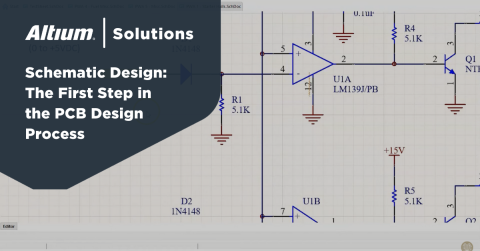
Schematic CAD software lets you select and arrange components in a schematic editor.
Advanced Schematic CAD Software Features
As your need for larger and more complex schematic designs grow, your schematic design program needs to be able to grow with you. Advanced electronics tend to have more than one complex schematic diagram, where different circuits are placed in multiple sheets. These schematics are linked together using hierarchical schematics, which define the parent-child relationships between different portions of circuit boards.
Your schematic CAD software should also include multi-channel design as this makes design reuse extremely easy. You can define different schematics as objects, just like a regular component model. You can then link each schematic diagram in a hierarchical fashion without copying and pasting circuit diagrams between multiple schematics.
This helps you remain productive, but you can only use this type of schematic editor in a unified design environment. In this environment, the underlying design engine and data model allow your design data to be transferred from a schematic to a new PCB layout. You’ll be able to do much more as you move toward the completion of your design.
Generate a Bill of Materials in Your Schematic CAD Software
As you prepare to finish your schematic and create your layout, you’ll need to create a bill of materials that shows your part numbers, quantities, and prices. The symbols you place in the schematic need to be loaded with data from your PCB libraries, which are then imported into your bill of materials for PCB manufacturing. When you can access part vendors for current pricing and availability during schematic design, you can prevent redesigns and move easily to PCB manufacturing.
These parts also need the physical attributes within them to drive the layout in addition to the logical attributes embedded in them for simulators and signal integrity tools. Creating a schematic is no longer a casual affair and requires a robust set of design tools that can accomplish all of these tasks.
- As your design grows, so will your schematic. Using hierarchical schematics allows you to organize multiple schematics for complex devices.
Learn more about hierarchical schematic design and how it can help you.
- There’s no need to reinvent the wheel when creating your schematics. Take a look here at reuse ideas and how they can help you in your next PCB design.
Learn more about schematic design reuse and ways to use it in your next design.
- If you have designs in other systems, it’s not a problem to translate them into Altium Designer’s unified design environment.
Learn More about converting a schematic diagram from other systems to Altium Designer.

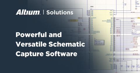
Hierarchical schematic design program features help you stay organized when creating large designs
How Altium Designer’s Schematic CAD Software will Help You
Since you need advanced design tools to create more complex schematics, your schematic CAD software should include hierarchical and multi-channel design features to keep you organized and aid design reuse. Once you’re ready to start your PCB layout, you need to quickly capture your schematics on a blank board. When all this happens in a single program directly from your schematic and component data, you can stay productive and enjoy a streamlined design experience. This is the type of environment you’ll find in Altium Schematic Designer.
Altium Designer: The Best Electronic Schematic Drawing Software
As you create your schematics in Altium Designer, you will have access to component data, design examples, and a SPICE-based simulator for pre-layout design evaluation. As your designs grow in complexity, Altium Designer gives you hierarchical and multi-channel schematic functionality to keep you organized and make reuse easy. The rules and constraints in Altium Designer form the core design engine in the schematic design editor, and your schematics will be checked against your electrical design rules as you create your board.
The rules-driven design engine allows your component data and design rules to be instantly imported into a new PCB layout. No other electrical schematic CAD schematic software provides these features and many more in a single program. The streamlined design experience helps you finish your design quickly and prepare for manufacturing.
- Altium Designer’s rules-driven design environment unifies schematic and PCB data into a single design process.
Learn more about Altium Designer’s unified schematic editor and PCB design rules.
- The schematic editor in Altium Designer allows you to create complex schematic program hierarchies and reuse designs in multi-channel schematics.
Learn more about creating hierarchical and multi-channel schematics in Altium Designer.
- The schematic capture tool in Altium Designer instantly creates a new PCB layout from your design data.
Learn more about schematics using schematic capture to create a new layout in Altium Designer.
No matter what types of circuit boards you’re working on, your PCB design software should include everything you need to transition to a complete PCB layout. Altium Designer has the power you need, the flexibility to advance with you as your designs grow, and rules and constraints to keep your designs error-free. Put down the pen and paper and pick up Altium Designer, the best schematic CAD software for PCB design.
Altium Designer on Altium 365 delivers an unprecedented amount of integration to the electronics industry until now relegated to the world of software development, allowing designers to work from home and reach unprecedented levels of efficiency.
We have only scratched the surface of what is possible to do with Altium Designer on Altium 365. You can check the product page for a more in-depth feature description or one of the On-Demand Webinars.


