


How to Use Class X and Class Y Safety Capacitors

At a Glance
Safety capacitors are used on the input stage of power supplies and on isolated power supplies to reduce EMI and ensure galvanic isolation at low frequencies.


Isolated power supplies make intentional use of different ground nets to keep power domains separate. This is partially done for safety and partially for EMC, although the two areas are somewhat related in certain industry standards. In order to control noise in these systems, we make use of a few important techniques as part of EMI filtering. One of these techniques is the use of so-called safety capacitors, also known as Class X and Class Y capacitors.
These capacitors are not special or unique. Just like a decoupling capacitor, the term “safety” refers to the function and placement of the capacitor, not to a specific type of capacitor. My mission in this article is to make you an expert on the usage of these capacitors. Let's dive in.
Where Safety Capacitors Are Placed
In isolated power supplies, safety capacitors are placed primarily in two locations:
- As a filtering element on the input line voltage
- As a net connection between galvanically isolated grounds
In the first case, Class X and Class y capacitors are placed in EMI filter circuits on the front end of a power supply. This could be in addition to a ferrite choke on the input power cable, as well as common-mode or differential-mode chokes in the EMI filtering stages.
Before we go further, let's get a few definitions out of the way. class X and class y capacitors are defined by their AC voltage ratings as specified in the IEC 60384-14 standard. Note that this standard is a performance-based standard, which means any capacitor that satisfies these requirements deserves the relevant X or Y classification in the table below.
|
Class Y AC Voltage Ratings |
Class Y AC Voltage Ratings |
|
Class X1: 2.5 kV to 4 kV (Peak pulse) |
Class Y1: Up to 500 V (8 kV peak test) |
|
Class X2: Less than 2.5 kV (Peak pulse) |
Class Y2: 150 V to 300 V (5 kV peak test) |
|
Class X3: Less than 1.2 kV (Peak pulse) |
Class Y3: 150 V to 250 V |
|
Class Y4: <150 V |
The main consideration regarding selection of these capacitors is whether they can withstand some target peak voltage value. For Class Y capacitors, the consideration is also the AC voltage amplitude. Based on these points, we can now see where these must be placed as part of input filtering.
Placement in Isolated Power Supplies
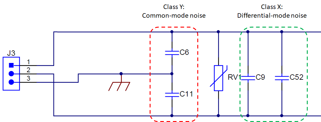
In isolated power supplies, Class X and Class Y capacitors are placed to address specific types of noise. Class Y capacitors are used to address common-mode noise by using a common shunt point to earth. For example, when used on an AC input to a DC power supply, one Class Y capacitor is used on each of the line and neutral connections to Earth, as shown below. The same type of connection to Earth could be used after a bridge rectifier, although this is very uncommon.
Class X capacitors are used to filter differential-mode noise in the same way, but they are connected across line and neutral. These capacitors are also shown below.
The other instance you would use one of these capacitors is to bridge the two galvanically isolated grounds in an isolated power supply. Normally a Class Y safety capacitor is recommended for this, but a Class X safety capacitor could also be used. The idea here is that the connection allows high-frequency noise currents to pass between the grounds as needed rather than allowing them to radiate their energy away from the PCB.
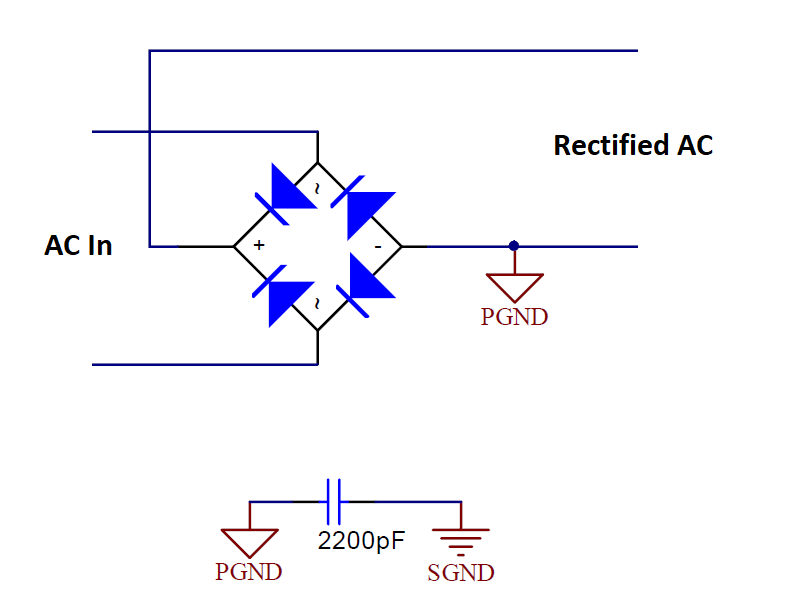
The capacitance requirement for this connection is that the safety capacitor’s value must be much larger than the parasitic winding capacitance. This usually means a Class Y capacitor with 1 nF to 1 uF will work, depending on the frequency range required to bypass to the primary side of the system. This ground net bridging connection is shown below. Note the location where PGND is defined on the output side of the bridge rectifier.
Notice the location where PGND is assigned: it is after the bridge rectifier! This is very important because we are connecting two DC grounds with the 2200 pF capacitor. If we connected it to neutral, we would have high AC voltage attached to the 2200 pF capacitor, which could destroy the capacitor.
Example Class X and Class Y Capacitors
Some example capacitors that could meet the IEC 60384-14 performance requirements are shown below. Parts like these are easy to find on Octopart; the best strategy is to start with a search based on the expected AC voltage protection requirement (for Class Y) or the pulse requirement for Class X. Some examples of Class Y capacitors are shown in the table.

What About Split Grounds in Mixed-Signal PCBs?
First things first, I’ll give the new designers out there the most important piece of advice:
Stop splitting ground into analog and digital planes. You will create more problems than you will solve.
I should probably tell people to keep doing it only because they will need to hire someone like me to fix the resulting EMI problems when planes are split. Thankfully, I care more about your pocketbook than I care about mine.
Isolated power supplies and boards with isolated ASICs like ADCs include these splits for very specific reasons. That does not mean you should be doing the same thing in your mixed-signal board just because it contains an ADC and an MCU. You’re better off just using a uniform ground plane.
That being said, there is a very specific instance of precision low-frequency measurements with low SNR values that sometimes works better with a split plane and a safety cap or ferrite bridging the two grounds. In that case, you can still use a capacitor or ferrite (or both) to control the return path and noise currents. If you don’t know how or why to do this, then don’t do it.
Whether your team is creating advanced prototypes or transitioning a new product into manufacturing, Altium Develop gives PCB designers everything they need to design for cost, quality, and comprehensively evaluate boards for electrical and thermal performance. Altium Develop unites every discipline into one collaborative force. Free from silos. Free from limits. It’s where engineers, designers, and innovators work as one to co-create without constraints. Experience Altium Develop today!

About Author
Related Resources
Related Technical Documentation
Table of Contents
Design to Release, Without the Friction
- Keep reviews tied to the right version
- Reduce handoff confusion and rework
- Spot sourcing and release risk earlier
- Work solo, share when needed
Get Started
Thank you, you are now subscribed to updates.

