


SMPS PCB Layout Guidelines in Altium Designer

At a Glance
We’ve got the SMPS PCB layout guidelines you need for power regulation in Altium Designer.


Many power electronics and embedded systems will need a custom regulator circuit. Lighting boards, laser diode drivers, many analog systems, and other noise-sensitive systems need low noise power regulation, and some COTS components simply won’t meet application requirements. This is especially true in power systems requiring precise output at high voltage/high current with little to no droop (e.g., electric vehicles). These systems use SMPS power supplies with switching regulators and standardized topology.
Getting your SMPS layout correct takes the best set of circuit design tools, and a PCB editor that takes data directly from your schematics. When you also have access to simulation features in your schematic editor, you can quickly qualify your design before you complete your layout. Altium Designer gives you all these features and many more in a single application. Here are some SMPS PCB layout guidelines to help you build the best power supply in Altium Designer.
ALTIUM DESIGNER
A unified PCB design package that integrates circuit design features with a powerful PCB editor and simulation features.
Simple power supplies are easy to design, but they won’t meet the performance requirements of many power electronics or embedded systems. Basic regulators don’t provide the required power efficiency, noise immunity, and low ripple for industry-standard applications. Many ICs have been designed to provide the required power output with low noise, but many high voltage or high current boards require a custom-designed switching regulator.
Building a custom regulator starts with selecting an appropriate power supply topology. Your topology will determine whether you can step up or step down the output voltage, and whether you’ll have some galvanic isolation in your system. You can go a step further and include some additional regulator circuitry to accommodate changes in the input level, such as what occurs when working with battery-powered systems. Let’s look at the various SMPS PCB layout guidelines and how you can design power supplies successfully with the right PCB design software.
Choose the Right Switching Regulator Topology
The three standard DC-DC switching converter topologies are boost, buck, and buck-boost (also known as flyback). Each of these offers major advantages over unregulated power supplies or linear regulators. The principle advantages of switching regulators are their higher efficiency and ability to control the output voltage with a PWM signal. The table below provides a comparison of the various regulator topologies.
|
|
|
|
|
|
|
|
|
|
|
|
|
|
|
|
|
|
|
|
|
|
|
|
|
|
|
|
|
|
|
|
|
|
|
|
|
|
|
|
Forward and flyback converters are sometimes mentioned interchangeably, but they are different topologies. These two types of regulators both use a transformer on the output stage for galvanic isolation, and the output voltage can be adjusted by changing the duty cycle of the PWM stream used for switching. A forward converter solves an additional problem of transformer core saturation and resulting hysteresis in a flyback converter’s transformer core. A forward converter also includes an additional diode and inductor on the output side, and it uses a three-winding transformer instead of a two-winding transformer.
Build Your Regulator Topology the Best Schematic Design Tools
Whichever regulator topology you choose to build for your next design, you’ll need a set of powerful schematic design tools to create your circuits. You’ll need access to a complete library of verified components that can be imported directly into SPICE-based simulations. When you work with design tools that unify your circuit design and simulation features in a single platform, you can create strong power supplies for any application.
- When you’re building a new switching regulator, you need to design and simulate all aspects of your new device with the best schematic editor.
See an example regulator project in Altium Designer. - In a switching regulator, your switching frequency will determine efficiency and ripple on the output. You’ll need to balance efficiency and noise by adjusting your PWM frequency.
Learn more about selecting the right frequency for your switching regulator. - Conducted EMI can propagate to the output from your power supply circuit unless you build an isolated power supply.
Learn more about building isolated power supplies.

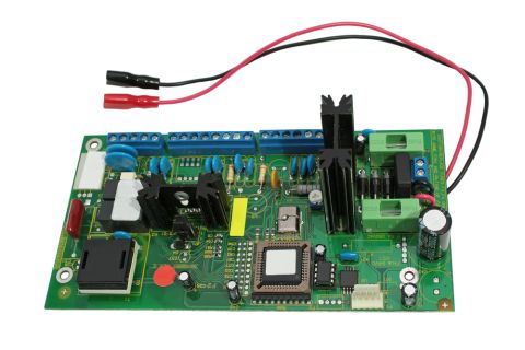
Starting Your SMPS PCB Layout
Once you’ve designed your SMPS circuits, you’ll need to capture your schematics as an initial layout and start arranging components. Designing for low EMI and stable power are critical aspects of your layout as you want your power output to remain as stable as possible. Thermal management can also be a challenge in high power circuits. Heat sinks and fans on critical components are important for keeping component temperatures within safe limits.
Keep Your Components Cool, Stable, and Noise Free
Your layout is the major determinant of crosstalk between different circuit blocks and power regulation problems once components start switching. Your PDN should always be designed with low impedance to suppress transients. You should always try to place decoupling components and other passive components such that circuits have minimum loop inductance.
Switching power supplies can generate significant noise when they run at high current, which can be received as noise spikes in your downstream circuits. If noise becomes a problem with passing compliance tests, you’ll want to filter as much noise as possible from the input and output of your circuits. This will go a long way to ensuring your power output remains stable once it reaches load components. These points will go a long way to suppressing noise and ensuring stable power distribution in your circuit board.
Power supplies can get very hot during operation, and you’ll need to take some steps to dissipate heat away from your SMPS circuits. This can be as simple as placing fans and heat sinks on important components. Be sure to opt for heavier copper in high current boards while following industry standards for power systems, specifically IPC-2152 and IPC-2221. With the right design application, you can define these requirements as design rules, and your ECAD application will automatically check your design against these rules as you create your PCB layout.
- Schematic capture is the first step in building your design and starting a new PCB layout.
Learn more about creating a PCB layout from a schematic. - Your power distribution network and component selection can affect SSN and ground bounce in your power system once load components start switching.
Learn more about analyzing your noise margin in SMPS design. - Your layout will determine how heat is transported around your power supply board and whether you can dissipate enough heat from your components.
Learn more about designing your PCB layout for thermal management.

The Best ECAD Software for SMPS PCB Layout
Most design programs force you to use separate schematic editors, routers, and simulators to produce a single product. This makes for an inefficient workflow and even forces you to use 3rd party design tools to complete a new design. Instead of working in this type of fragmented environment, you need to create your next SMPS circuit board in a unified design package.
When you work with unified design software, you’ll have access to everything you need to create a new product in a single application. This is the type of environment you’ll find in Altium Designer. Everything you need is in a single application, allowing you to go from concept to product with ease.
Design Your Next SMPS PCB Layout in Altium Designer
Altium Designer is the only PCB design and layout application that includes everything you need for SMPS design. You can design and integrate your SMPS circuits with a powerful schematic editor, and you can capture your schematic as an initial circuit board layout in the same program. You’ll have access to pre-layout and post-layout simulation tools, and you can quickly prepare deliverables for your manufacturer. No other PCB design application makes it so easy to take a new product to market with a single program.
- Designing your SMPS circuits, placing components, and routing traces are easy tasks in Altium Designer. The rules-driven design environment in Altium Designer instantly checks your SMPS PCB layout against your design rules as you create your circuit board.
Learn more about the integrated design environment in Altium Designer. - When you’re designing your circuits, the powerful schematic editor in Altium Designer gives you everything you need to find verified component models and simulate your circuits with a powerful SPICE-based simulation engine.
Learn more about the PCB design interface in Altium Designer. - All Altium Designer users can store and share their SMPS PCB layout designs through the Altium 365 platform. If you work on a design team, Altium 365 helps your team members stay productive and share design data in a secure cloud environment.
Learn more about sharing your PCB design data on Altium 365.

If you’ve never worked in an integrated design environment, Altium will be there with the resources you need to get started and design successfully. You’ll have access to the AltiumLive forum, webinars and podcasts with industry experts, a huge knowledge base with plenty of design tips, and design tutorials. No other PCB design software company is this invested in your success.
Altium Designer on Altium 365 delivers an unprecedented amount of integration to the electronics industry until now relegated to the world of software development, allowing designers to work from home and reach unprecedented levels of efficiency.
We have only scratched the surface of what is possible to do with Altium Designer on Altium 365. You can check the product page for a more in-depth feature description or one of the On-Demand Webinars.

About Author
Related Resources
Related Technical Documentation
Table of Contents
Design to Release, Without the Friction
- Keep reviews tied to the right version
- Reduce handoff confusion and rework
- Spot sourcing and release risk earlier
- Work solo, share when needed
Get Started
Thank you, you are now subscribed to updates.