








Wake-Sleep Timer Control With Mixed Signals

At a Glance
Wake-Sleep Timers Can Help Reduce Power Consumption, but They Are Hard to Implement in Systems With Many Peripherals. You Can Do This Very Easily With a Custom Mixed-Signal ASIC From the GreenPAK.


The simplest way to conserve power in a system is to shut down all the peripherals. By shutting down processor cores or logic circuits, you reduce baseline current or quiescent current to zero outside of the system power controller. This type of power conservation can be performed automatically with a set of GPIOs, which may be implemented in an embedded application.
While this may sound like a very simple function to implement, the resulting circuitry and effect on a device's code base may not be so simple. Most often, we rely on wake-sleep functionality in specific devices that are known to be major power consumers, such as a large microcontroller or FPGA. In particular, for microcontrollers, these functions have become more common and they are certainly useful for shutting down an embedded system.
However, for a collection of ASICs, a wake-sleep function is rarely built into a device, and there are often other peripherals which could not be shut down even if this feature were built into your ASICs. At that point, you're now adding a complex microcontroller, timer, and reset to control your system. Instead, take a look at this application example for GreenPAK, which allows wake-sleep timer functionality to be implemented and triggered based on any set of logical conditions.
How a Wake-Sleep Timer Works
Wake-sleep timers, whether implemented as part of an integrated circuit or custom designed into a PCB, all perform two basic functions:
- Capture a signal that triggers the wake-up functionality
- Run a timer and shutdown sequence after a time limit is exceeded
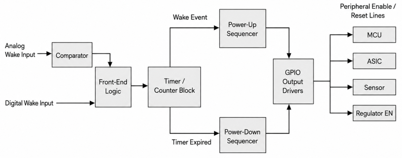
This seems simple enough until you count up the list of circuits required: the power shutdown sequencer, a power startup sequencer, delay timers, either a digital or analog front end to detect the wake signal, and peripherals that allow shutdown from toggling by a logic signal. This is summarized in the block diagram below.
The basic block diagram for a wake-sleep timer includes a front-end detection stage that captures the wake signal, a timer block that counts down the active period, a sequencer that controls the power-up and power-down ordering of peripherals, and output drivers that assert enable or reset lines on downstream devices. The front end feeds into the timer, which upon expiration triggers the shutdown sequencer; upon receiving a new wake event, the startup sequencer re-enables peripherals in the correct order.

In the purely digital domain, the wake signal is effectively a single bit (or set of bits) at the required logic level, which asserts the input(s) on the front-end logic circuit of the wake-sleep circuit. For an analog wake signal, some front end is needed that is designed specifically for the signal in question, essentially taking some measurement of the signal (amplitude, phase, frequency, etc.) to determine whether the wake condition has been satisfied.
Wake signals can be supplied by effectively any type of source as long as the front end in the wake-sleep timer is designed to support it. This opens the opportunity for mixed-signal interfaces, where digital and analog inputs are used to trigger the wake conditions in the wake-sleep timer.
Can Mixed Signals Be Used in Wake-Sleep Timers?
The answer to this question is yes in general, but it adds complexity to a standard wake-sleep timer circuit. A wake-sleep timer normally operates on a single digital input, or a single analog input that has passed a threshold as detected with a comparator. For example, this could be an indicator output from a touch device or a button, or it could be a sensor output that exceeds some voltage level. In general, multiple signals could be combined into a single front-end interface as part of the wake condition for this circuit.
However, this requires an additional logic processing block at the front end of the wake-sleep timer. The simplest solution is implemented with logic gates, and any input analog signal could be digitized with a comparator. One might consider using a microcontroller for this task, but it defeats the purpose of a wake-sleep timer, which is generally to shut down peripherals and digital processors.
Mixed-Signal Processing for Wake-Sleep Signals
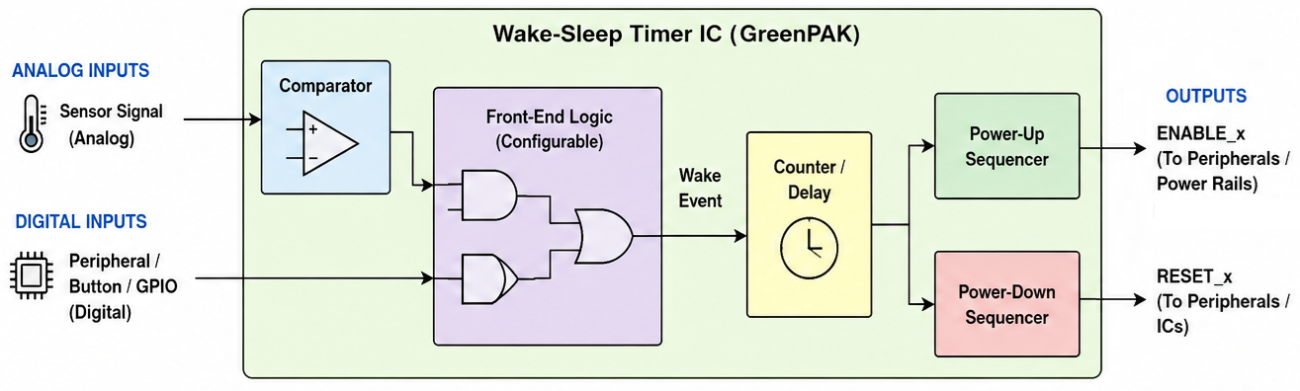
The Renesas GreenPAK programmable mixed-signal IC is well suited to implementing a wake-sleep timer because it integrates analog comparators, logic gates, counters, delay blocks, and configurable I/O within a single device. A fully custom mixed-signal interface can serve as the front end for the wake-sleep timer, accepting both digital and analog inputs simultaneously.
For instance, an analog comparator inside the GreenPAK can monitor a sensor voltage while a separate digital input watches for a logic-level event from a peripheral; these signals feed into configurable logic that evaluates the combined wake condition. Once the wake criteria are met, internal counter and delay blocks manage the power-up and power-down sequencing of external rails or reset lines.
The Go Configure developer tools give designers the ability to develop fully custom wake-sleep timers that can implement mixed signals and even a serial interface as part of the wake functionality. These programmable mixed-signal processors allow for smaller, more efficient systems.
To learn more, take a look at the GreenPAK components and reference examples.
Whether you need to build reliable power electronics or advanced digital systems, use the complete set of PCB design features and world-class CAD tools offered by Altium to implement your GreenPAK solutions. Altium provides the world’s premier electronic product development platform, complete with the industry’s best PCB design tools and cross-disciplinary collaboration features for advanced design teams. Contact an expert at Altium today!
Related Resources
Related Technical Documentation
Thank you, you are now subscribed to updates.