







What Makes a Smart Reset Controller IC?

At a Glance
Complex electronics often demand a complex system reset procedure in the event of faults or when users require a my preset. Here's how you can implement system resets without a microcontroller.


Many complex devices use multiple subsystems, often with their own power, screen processing blocks, and sensory interfaces. They may also demand always-on functionality, such as we have in many consumer devices and medical devices. It's easy to provide always-on behavior, but it's not so easy to implement a controlled system reset in the event of a fault or when a user demands a system restart.
Most common reset solutions we have seen in the past are implemented on small microcontrollers. While microcontrollers are certainly capable, they often require peripherals to implement a full reset solution, and they leave many unused pins, even on the smallest components. There's also the issue of mixed-signal sensing, which many small microcontrollers cannot perform and will require an external comparator bank or ADC.
Instead of designing a circuit around a microcontroller and writing dedicated firmware to run the solution, system resets can be much more readily performed with a mixed-signal processor like GreenPAK. These solutions are firmware-free and are programmed as silicon, making them a truly superior option compared to system resets performed with microcontrollers.
Basic Reset Controller Functions
Not all electronic devices need reset control; they can simply be power cycled and will always start up to the same state without guidance, saved data, or processing. Many designs that implement digital processing and integrate peripherals through multiple ASICs are very different, requiring a specific timing sequence and order to turn on/off peripherals or subsystems during power-up and power-down. Reset controllers help implement this process, ideally with a single-chip solution.
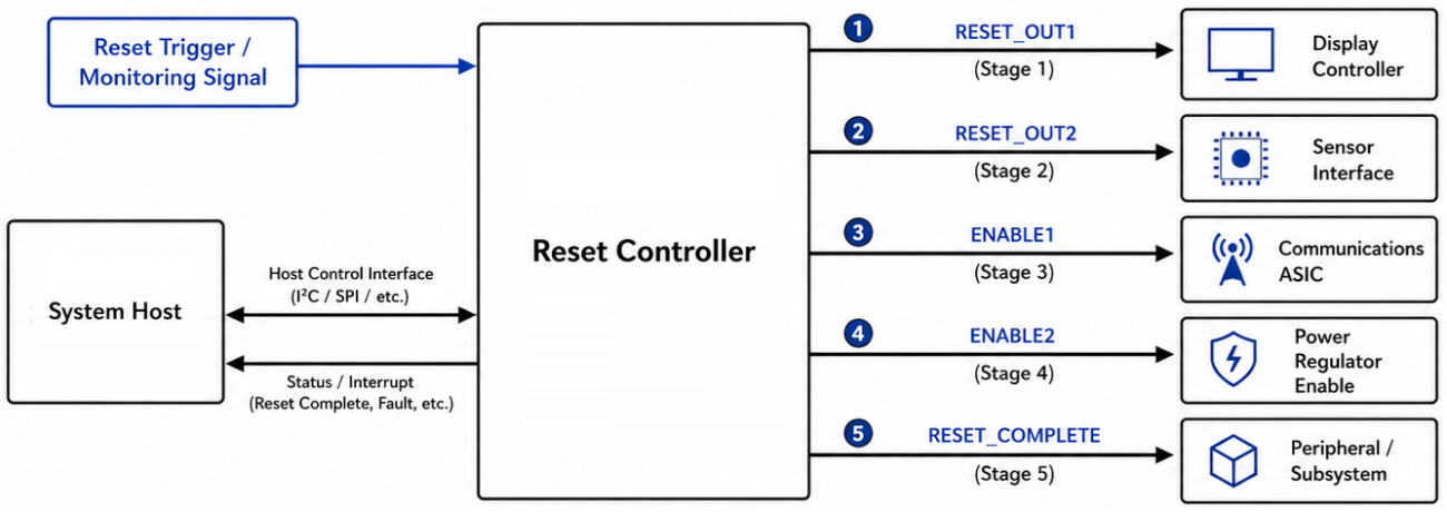
Simple system reset controllers will monitor a GPIO, output from an ADC, or comparator output, which effectively acts as a trigger or indicator for the reset condition. Once triggered, the reset controller must execute a defined sequence of actions to bring the system and its peripherals through a controlled shutdown and restart. The specific responsibilities of the reset controller after triggering typically include:
- Asserting reset or enable lines to each peripheral or subsystem in the correct order, following the timing requirements defined by each device
- Holding each reset line active for the minimum duration specified by the downstream component
- Sequencing power-down signals so that dependent subsystems shut down before their supply rails are removed
- Re-enabling power rails and releasing reset lines during power-up in the reverse order, respecting any required delay intervals between stages
- Providing a status or "reset complete" output to the system host once the full sequence has finished
What Makes a Smart Reset Controller?
A reset controller gets "smarter" once it can read more indicator signals, process those logically, and arrive at the required trigger condition before beginning the reset process. In general, simple reset controllers require a digital input as part of the reset trigger. More advanced reset controllers can take in multiple types of signals:
- Pulse trains
- DC analog signals
- Digital signals at standard logic levels
- Analog measurements from an ADC
- Rectified AC signals
- Commands over a serial interface
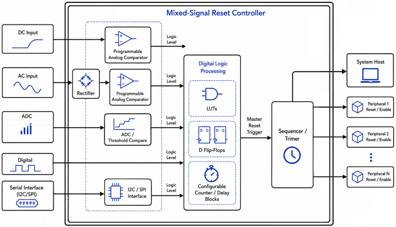
In more complex mixed-signal systems, any (or all) of these types of signals could be used as an indicator for triggering a system reset. A smart reset controller not only needs to accept any of these signals as inputs, but also process them in digital logic in order to trigger the reset sequence. The reset controller then needs to implement the precise set of timing controls and toggle signals to reset the system.
How Mixed-Signal Processing Works in Reset Controllers
The core challenge in a mixed-signal reset controller is converting diverse analog indicators into logic-level signals that can participate in deterministic digital decision-making. Analog inputs rarely arrive in a form that digital logic can use directly, so the front-end of the reset controller must condition each signal before it reaches the logic processing stage.
For DC analog signals such as a voltage rail or a sensor output, an on-chip comparator compares the measured level against a programmable voltage reference. When the signal crosses the threshold, the comparator output transitions to a logic HIGH or LOW, producing a clean digital indicator. For AC signals, the path is slightly longer: the signal is first rectified on-chip to produce a DC envelope, and that envelope is then evaluated by a comparator against a reference. ADC-based measurements follow a similar pattern, where the digitized result is compared against a stored threshold to generate a logic output.
Once every analog input has been reduced to a logic-level indicator, the controller's digital processing block takes over. This block typically contains the following elements:
- Lookup tables (LUTs) that combine multiple logic indicators into composite trigger conditions
- D flip-flops and latches that store state information and synchronize asynchronous inputs
- Configurable counters and delay elements that enforce timing requirements, such as debounce intervals or minimum hold times before a reset is confirmed
The table below summarizes the signal conditioning path for each input type.
Input Signal Type | Conditioning Stage | Output to Logic Block |
DC analog voltage | Comparator vs. programmable reference | Logic HIGH/LOW |
AC signal | Rectification, then comparator vs. reference | Logic HIGH/LOW |
ADC measurement | ADC conversion, then digital threshold compare | Logic HIGH/LOW |
Digital GPIO | Direct connection (with optional debounce) | Logic HIGH/LOW |
This architecture ensures that every input, regardless of its original domain, enters the digital logic stage as a uniform logic-level signal. The LUTs and sequential elements then evaluate the full set of conditions and, when the programmed trigger criteria are met, initiate the reset output sequence with precise timing control.
Use GreenPAK for Smart Reset Controllers
Renesas GreenPAK simplifies smart reset controller design by integrating the full mixed-signal front-end and digital logic into a single programmable device. On-chip comparators, voltage references, and ADC inputs handle DC levels, AC envelopes, and threshold detection without requiring external analog components like comparator banks or reference dividers.
Configurable LUTs, flip-flops, and delay elements execute precise reset sequences directly in silicon. Without additional firmware to maintain or boot time delays, GreenPAK provides a reliable, firmware-free solution that saves board space and reduces development time compared to traditional microcontrollers.
The Go Configure developer tools give designers the ability to develop fully custom system reset controllers that can implement mixed signals. These programmable mixed-signal processors allow https://www.renesas.com/en/products/programmable-logic/greenpak-programmable-mixed-signal-products/greenpak-solutions/reset-icfor smaller, more efficient systems.
To learn more, take a look at the GreenPAK components and reference examples.
Whether you need to build reliable power electronics or advanced digital systems, use the complete set of PCB design features and world-class CAD tools offered by Altium to implement your GreenPAK solutions. Altium provides the world’s premier electronic product development platform, complete with the industry’s best PCB design tools and cross-disciplinary collaboration features for advanced design teams. Contact an expert at Altium today!
Related Resources
Related Technical Documentation
Thank you, you are now subscribed to updates.

