


Draftsman: Make the Software Do the Documentation


You’ve routed your last route. Stitched your last via. Poured your last pour. You’re finally done with that board — time to celebrate! (Or at least move on to the next project.)
Hang on! You’re not done yet.
There’s still the documentation to be done – the fab drawings, the assembly CAD drawings, everything the fab shop needs to turn your carefully crafted work of art into a real electronic product. Unfortunately, the tools you have access to in your PCB layout software are going to make this a long, manual, and possibly error prone process. Why is that? EDA vendors have spent years and years and lots and lots of money improving the PCB design process. Routing is faster and easier than ever. Footprint creation? No sweat. Got wizards for those. But getting your CAD drawings created? Now we’re back to the ‘90s (or even the ‘80s).
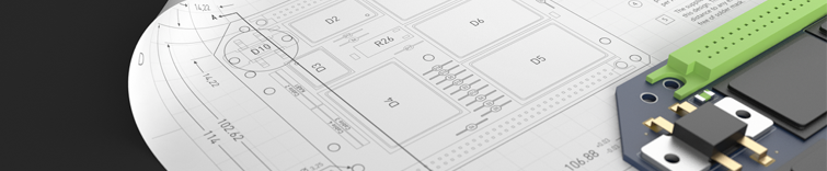
Image courtesy of PCB Design School [1]
Documentation: The Bad, The Worse, The Ugly
Over the years I’ve heard estimates about how much of a design cycle is eaten up by the documentation process. The conservative numbers are as low as 10% but I’ve seen other stats that say up to 40%! That’s a staggering amount of time to spend on something that doesn’t add any value to your design. That’s right – good documentation adds absolutely NO value to your design. It won’t make it any better than what you’ve put into your PCB design system. The best it can do is properly and accurately take what you’ve done and transfer it to paper or virtual paper in the form of a print to file (PDF). You should be spending as little time on this as possible, so you can get back to what you have a passion for (and get paid for) — designing. Of course, you don’t want to cut corners either. The consequences of poor documentation can range from time lost resulting from back and forth emails and phone calls with the fab shop to incorrectly produced boards. Neither of those makes you look good.
Well, no use complaining about it. Let’s get going on that drawing editor. Hopefully you’ve got your sheet border saved off in a library somewhere. Otherwise you’re in for an exciting hour of hand drawing. Maybe your MCAD guy has something that you can DXF in. Copy and paste from the last design? I guess that’ll have to do. (Wait, was that the one the board house called you back about because the fab notes called out an old IPC spec?) It’ll have to do. Moving on!
Let’s create an assembly drawing with the top and bottom views of the board. All on one sheet? Nope. Can’t do it that way. Add some side views to see the profile of board since you added all those nice STEP models to your PCB. In the same file? Hmm — can’t seem to do that either. You’ll have to settle for a JPEG. Maybe more copy and pasting is in order. What layers need to be turned on to get the CAD drawing that you want? Hard to tell with this tiny preview window that doesn’t show any detail. Just print to file (PDF) and take look. Not right? Just do it over. You’ve got time.
The fab drawing editor is pretty straightforward. How hard can that be? You may want a layer stack cross-section. Just hope that the board stackup doesn’t change in the next design revision because you’ll have to redraw it from scratch. If you had the time, you’d draw cross-section graphics of all of your typical layer stacks and put them in a library somewhere. But you don’t have the time, do you? There are plenty of ways of making your processes more efficient but having been in this industry for over 20 years, one thing I’ve seen over and over is that very few people make the time to become more efficient. Why? You know the reasons. There’s always another project to move on to, you’re fighting with your software and wasting time with manual processes like documentation, and so on.
Making Documentation Work for YOU
So instead of we as designers having to become more efficient, let’s ask for our tools to be more efficient. Documentation automation tools DO exist! Most are third-party or add-on tools to your current PCB flows. But isn’t documentation a requirement to get your products created? Why should you have to pay extra to create the outputs you need?

Draftsman® is a dedicated documentation authoring environment included as part of the Altium Designer® standard PCB license. Because of our unified design environment, it reads the board data directly from the PCB. Standard border templates are provided, which can be edited per your company’s requirements and centralized in your Altium 365 workspace, ensuring consistent use across your organization. From there, the designer can easily add and manipulate a variety of views to quickly construct accurate and detailed fab and assembly drawings. All facets of the PCB are available for inclusion, including copper, mechanical component model details, layer stack information, BOM data, and more. Even assembly variants are supported. And when an ECO comes along, there’s no need to regenerate anything. Just update the Draftsman software document with the current PCB design and everything will update accordingly. Then just add the Draftsman software document (or documents) as part of your Output Job file for a complete and repeatable design release package.
When you’re ready to streamline your design and production workflow, use the world-class CAD features and automated PCB assembly drawing tools in Altium Designer®. You and your team can create advanced designs and quickly prepare them for manufacturing while staying productive and efficient. When it's time to release your designs to production, use the complete set of release management features in the Altium 365™ platform to collaborate with your manufacturer. Everything you need to design and produce advanced electronics can be found in one software package.
About Author
Related Resources
Related Technical Documentation
Table of Contents
Design to Release, Without the Friction
- Keep reviews tied to the right version
- Reduce handoff confusion and rework
- Spot sourcing and release risk earlier
- Work solo, share when needed
Get Started
Thank you, you are now subscribed to updates.

