


Flyback Transformer Design With Core and Coilformer

At a Glance
Flyback transformers can be designed as custom components with high efficiency and galvanic isolation. Here is how to create a custom flyback transformer for a flyback converter.


In this article, I'll run over the design process used to determine the transformer design parameters required in my earlier custom flyback converter project. In this design project, I designed a flyback converter that takes AC input, rectifies it to DC, and steps it down to a 3.3 V output. The converter is based around a Texas Instruments UCC28881. As is the case with many isolated switching converters, a custom transformer was needed for the design.
The WEBench tool from Texas Instruments provides design guidance and a core/coilformer recommendation for this design. In this design process, I'll use their core and coilformer recommendation to complete the transformer design. I’ll also calculate the physical parameters for the designed transformer.
Getting Started With a Custom Transformer Design
In an isolated switching converter, I think the best strategy to determine the required transformer parameters is to start from the secondary (output) side and work your way to the primary side, as well as any tertiary coils. We will start with the following process:
- Verify the primary inductance based on the PWM frequency and duty cycle
- Use the inductance and voltages to determine the turns ratio
- Determine the number of required turns based on the core’s material properties
- Verify that the coilformer size will work based on required wire gauge and window area
One important point to note in this process is that some of the parameters are free for you to determine. For example, you can select switching frequencies and a target minimum/maximum PWM duty cycle based on your switcher's capabilities. Your inductance may need to adjust to accommodate required changes in these parameters.
Next, based on the average current and average power delivery, there may be constraints on the wire gauge size that can be used in the coilformer. Higher average current will demand larger wire gauge in order to prevent the transformer from heating up too much. So if you want your transformer to deliver more power with higher average current, then you will need a physically larger transformer.
With that in mind, let's jump into the inductances.
Primary and Secondary Coils (Discontinuous Mode)
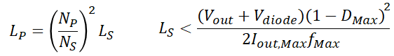
First, we can calculate the primary and secondary coil inductances as follows:
The L(s) equation denotes discontinuous current mode operation; change the direction of the inequality and you will have continuous mode operation. V(diode) is the rectifier diode’s forward voltage on the secondary side.
In this equation, we want to determine the limit on secondary inductance that will allow the switcher to continuously regulate the output voltage. In voltage-mode control, the switcher will adjust the duty cycle, so you need to use the maximum duty cycle and frequency in order to size the upper limit on the inductances. The maximum current output and the secondary voltage are nominal values.
Turns Ratio and Actually Duty Cycle
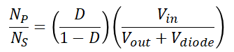
Next, we need to determine the turns ratio and the actual duty cycle at which the converter is required to run. As long as the actual duty cycle is less than the maximum duty cycle for your switcher, then the inductance on the secondary side will not be too large to maintain regulation and the design should be viable.
This equation gives you a relationship between the turns ratio and the duty cycle. Remember, the switcher could run at any duty cycle up to its maximum, and the control loop will adjust the PWM duty cycle based on the measurement of the output voltage. When you know the duty cycle, plug that into this equation to get the required turns ratio.
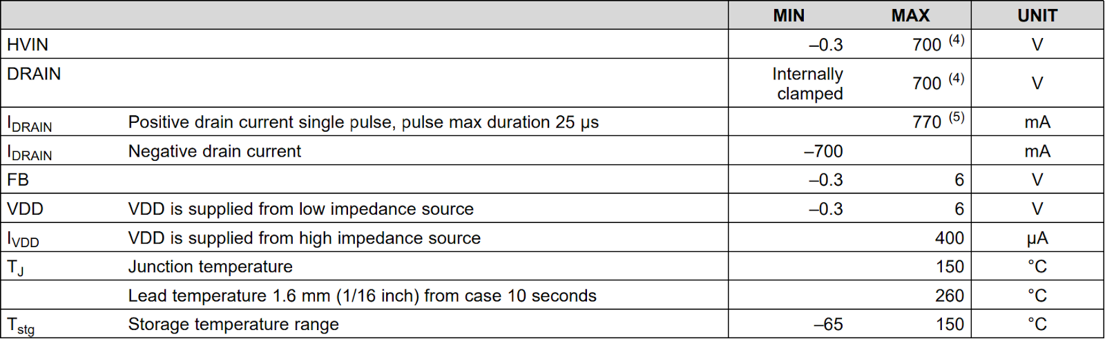
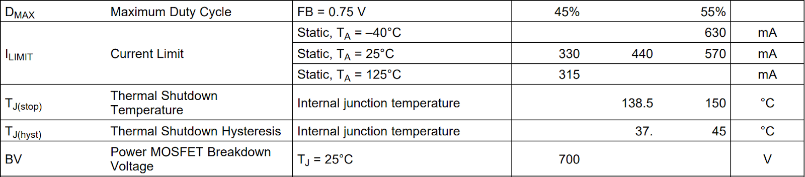
Next, it is useful to know the peak current on the primary side as this is the peak current that will be flowing through the switcher. This is important because some switchers may have overcurrent protection, and this includes the UCC28881. Now we need to use the peak current specification, target duty cycle, and turns ratio values to check the peak currents. For the UCC28881, the peak primary current limit before shutdown is shown below (440 mA continuous, 770 mA pulsed).
In the next section, I’ll use the maximum pulsed current limit with some derating to check that the design can meet my specifications.
Checking the Math
Here, my intention is to design the converter and its transformer so that the maximum duty cycle of 50% corresponds to half the allowed peak current, which will give me plenty of derating. Now that we have these equations, we can plug in some numbers and determine the turns ratio.
- Input values:
- Maximum V(In) = 240 V AC RMS
- f = 62 kHz, D(max) = 0.5 (based on average value from datasheet)
- D(target) = 0.3 (chosen by design)
- I(pk, primary) = 0.385 A, I(Avg, primary) = 0.116 A
- Schottky rectifier diode forward voltage: V(diode) = 0.5 V
- V(out) = 3.3 V
- Output values
- Based on D(target), Np/Ns = 19.17
- I(pk, secondary) = 8.45 A, I(Avg, secondary) = 2.54 A
- L(s,max) = 3.02 uH
Based on these numbers, the design is viable and the converter should have no problem supplying our target output current as long as we can hit the target coil inductances. This is now where we have to look at the core and coilformer to ensure the target inductances can be reached.
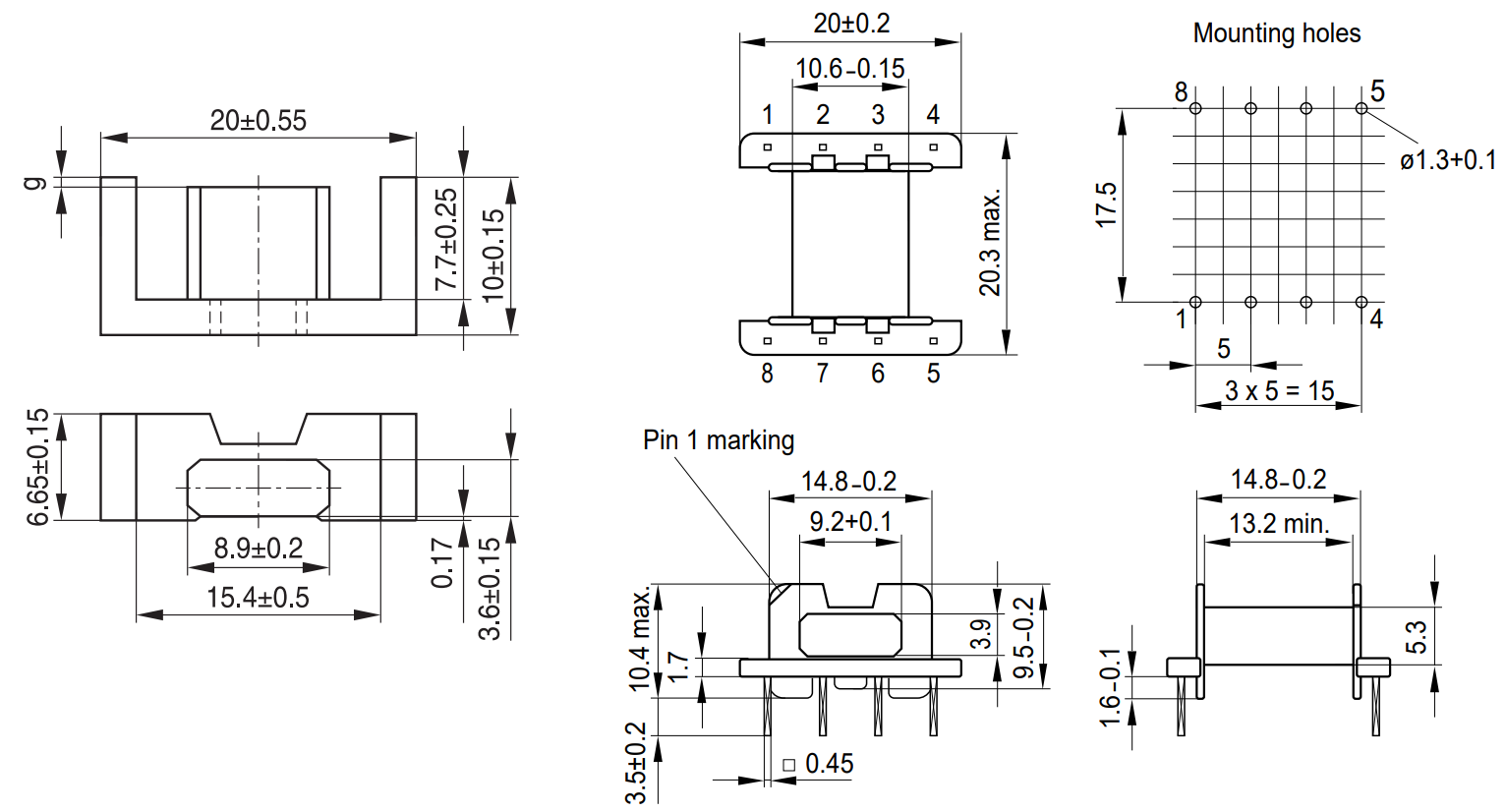
Off-the-Shelf Core and Coilformer
Now that we know the inductance target and turns ratio, we can start to select a core and coilformer to build the transformer. As I mentioned above, higher output current will limit the wiring that you can use to wind the coil, so this will certainly be a consideration When selecting core and coilformer.
At this point, you are free to look online for core and coilformer sets that will help you hit your inductance target. The coilformer, core, and yokes recommended by Texas Instruments are:
- Coilformer (QTY 1): B66418W1008D001
- Air-gapped E-core section (QTY 2): B66417U0250K187 or Ungapped E-core section (QTY 2): B66417G0000X149 with 2 winding layers
- Yoke (QTY 2): B66418B2000X000
In the core data sheet, you will see a specification called the inductance factor. The inductance factor essentially tells you the inductance per number of turns around the core, assuming you are using the recommended coilformer. Based on the turns ratio listed above and the current requirements listed above, we could use AWG 26 wire with 3 turns for the secondary coil, and AWG 30 wire with 57 turns for the primary coil (wrapped in 2 wire layers). This gives:
- L(s) = 2.25 uH
- L(p) = 812.25 uH
These are a bit lower than the TI recommended values from WEBench, but they are within the typical winding inductance tolerance values for a transformer, so I mark them as valid for a discontinuous mode design. If you wanted to change the operation mode to continuous, you would only need 2 more windings on the secondary side. This would also reduce the flux density on the secondary side.
Additional Verification
One verification step is to determine whether the wire gauge you select will overfill the coilformer. Using the sheath diameter for your wiring, calculate the total distance spanned by the coils. If this number exceeds the length of your coilformer, then you need to use a larger coilformer or smaller wire diameter. The latter may require you to reduce the allowed current in your secondary side in order to keep temperature down.
The last verification will be a comparison of the flux density to the saturation flux in your core material. This is where support from a core material provider will be very important as these values are not always stated in a datasheet. At saturation, the efficiency starts to greatly decrease, so you need to ensure that your flux density is below the saturation density. This is one reason why we actually want more turns in the coil rather than fewer turns. We also might want to use a core material with smaller permittivity as this also reduces flux density.
Whenever you want to build stable and reliable power systems, use the complete set of PCB design features and world-class CAD tools in Altium Designer®. To implement collaboration in today’s cross-disciplinary environment, innovative companies are using the Altium 365™ platform to easily share design data and put projects into manufacturing.
We have only scratched the surface of what’s possible with Altium Designer on Altium 365. Start your free trial of Altium Designer + Altium 365 today.

About Author
Related Resources
Related Technical Documentation
Table of Contents
Design to Release, Without the Friction
- Keep reviews tied to the right version
- Reduce handoff confusion and rework
- Spot sourcing and release risk earlier
- Work solo, share when needed
Get Started
Thank you, you are now subscribed to updates.


