Guide to Ceramic Capacitor Dielectrics and Other Types
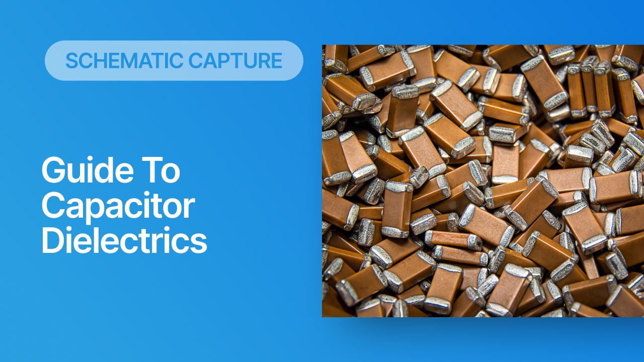
Capacitors form an important part of most electronics circuits. But what do they actually do, and what causes them to function as such? They are passive devices that store electrical potential energy as a voltage between two charged conductors that are separated by an insulating dielectric. The insulating dielectric material restricts DC current and allows AC current to induce a displacement current across the two plates as mediated by polarization in the presence of an applied voltage. These components find their way into everything from analog filter networks to power supplies and high speed digital components.
What helps capacitors achieve the function that they are intended to perform? The strength of the electric field in the capacitor dielectric determines how displacement current arises through the device, thus we can categorize capacitors based on their insulating dielectric. In this article, we discuss the categorization of capacitor dielectrics, including a section dedicated to ceramic capacitor dielectrics.
Common Capacitor Dielectrics
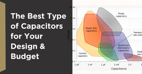
There are several types of capacitor dielectrics, each coming in a variety of package sizes. Some materials generally have much higher dielectric constant than others, and they can be considered to have a higher “capacitance density”, meaning they provide higher capacitance in smaller packages. Designers who have looked at the inside of a power supply have probably seen large radial capacitor packages that stand vertically on the board; these are electrolytic capacitors, and they require packaging of this size in order to provide such high capacitance values.

Other capacitor dielectrics have other advantages beyond providing a high capacitance density. They can have very high breakdown voltage rating, they may be very useful for AC as they do not require a specific polarity, or they can have a very low temperature coefficient that makes them a better option for precision applications. This is one reason why datasheets and app notes will recommend selecting capacitors based on their dielectric material rather than based on an actual capacitance value. In those applications, the capacitor value could matter less than the specific advantages of the capacitor dielectric material itself. Keep this in mind when you see capacitor recommendations in datasheets or application notes.
Types of Capacitor Dielectrics
Ceramics
The capacitance of ceramic capacitor dielectrics is impacted by temperature and applied voltage. They also have lower DC leakage current values and lower equivalent series resistance (ESR). Ceramic capacitors tend to be non-polar and hence can have any orientation in a PCB layout; this is one reason why they are preferred in high frequency AC and power applications. However, their low ESR can allow strong transients in power systems, something which could be avoided with a controlled ESR capacitor.
Ceramic capacitors are made by coating two sides of a small ceramic disc with a metal film (such as silver) and then stacking them together in the capacitor packaging. A single ceramic disc of about 3-6 mm can be used to reach very low capacitance. The dielectric constant (Dk) of ceramic capacitor dielectrics is very high, so relatively high capacitance can be obtained in small packaging.
Electrolytic (i.e., tantalum, aluminum, etc.) or oxide dielectrics
These capacitors are used in circuits where the required capacitance is very high. Here a semi-liquid electrolyte solution in the form of a jelly or paste is used as a replacement to a very thin metallic film layer that serves as the cathode. These are more stable in terms of capacitance (e.g., tighter tolerances and temperature variation), and they are more stable at high voltage. They have higher ESRs than ceramic capacitors and are unpolarized.
Plastic film
These capacitor dielectrics tend to have lower Dk value and hence much larger size, but they are very useful in high-frequency circuits. Film capacitors are the most commonly available type of capacitor, involving a relatively large family of capacitors with various dielectric characteristics. Therefore, there can be a wide range of material specifications for these capacitors.
PCB substrates
Technically, a PCB is a big capacitor whenever it contains large adjacent plane layers. Planes in a PCB can provide about 50 pF/sq. in. of capacitance with very low ESL, which is why plane capacitors are often the most effective form of capacitor you can use for decoupling package-induced transients in the PDN of a high speed PCB.
Ceramic Capacitor Dielectrics and their Strength-based Categorization
The Class of a ceramic capacitor depends on its dielectric strength, which determines the breakdown voltage in the capacitor dielectric.
- Class 1: Class 1 ceramic capacitors are commonly made from oxide materials additives of Zn, Zr, Nb, Mg, Ta, Co, and Sr. These capacitors would be chosen in applications that require an AC circuit that is relatively insensitive to temperature changes. An example would be in resonant circuits like filters or matching networks where a product needs to have high precision in harsh operating conditions.
- Class 2: These ceramic capacitors are made from a barium titanate base dielectric material, which is temperature-sensitive. These ceramic capacitors have high capacitance density, i.e., you can reach a high capacitance in a small volume. In general, class 2 ceramic capacitors are used for smoothing, bypassing, coupling, and decoupling applications.
- Class 3: This group of ceramic capacitor dielectrics provides high capacitance compared to Class 2 ceramic materials. Class 3 capacitors are considered outdated and are no longer standardized by IEC. Modern Class 2 multilayer ceramic capacitors can offer higher capacitances with better stability and tighter accuracy in a more compact package.
Note that the above definitions are standardized in IEC/EN 60384-1 and IEC/EN 60384-8/9/21/22. The EIA has its own set of definitions with four classes of ceramic capacitor dielectrics. Each class is denoted with a Roman numeral, so keep this in mind if you see product pages that define a capacitor as Class 3 vs. Class III; these designations are not equivalent.
Capacitor Coding System
There is a three-character alphanumeric coding system used to designate ceramic capacitors, with the system depending on the class of ceramic. Additional code markings on the case of a capacitor may indicate the rated operating voltage, tolerances, and temperature coefficient.
As an example, class 2 ceramic capacitors are categorized by their operating temperature limits and the sensitivity of the capacitance to temperature changes. The sensitivity value is rated within the upper and lower temperature limits and is not guaranteed outside these limits. Note that these codes aren’t names given to ceramic capacitor dielectric materials. Ceramic compounds could be a proprietary product name or a chemical compound name. Instead, these codes are used to match an application area to a required tolerance level.
The table below shows the characters in the 3-character naming code for Class 2 ceramic capacitors (X5R, X7R, etc.).
|
|
|
|
|
|
|
|
|
|
|
|
|
|
|
|
|
|
|
|
|
|
|
|
|
|
|
|
|
|
How to Find Capacitors With Specific Dielectrics
If you’re looking for capacitors with an electrolytic, plastic, or even polyester dielectric, you can just search for these in your PCB parts library tools. A service like Octopart can show plenty of options with specific dielectrics, case sizes, mounting styles, etc. There are a few main points to consider when selecting dielectrics:
- Capacitance and temperature coefficient: Both of these points should be considered together when doing a dielectric-based component search.
- Tolerances: This is not the same as the temperature coefficient; it is the variation around the rated capacitance value (just like in other passives).
- Lifetime: Capacitor dielectrics have a lifetime limitation, where the capacitance will slowly decrease over time and eventually will change beyond the limit defined by the device’s tolerance level.
- Parasitics: ESL and ESR are important for high-frequency applications, in some power applications involving fast switching, or power integrity for digital systems.
- Case size: For chip capacitors and radial/axial electrolytics, larger cases give larger capacitances. These may follow a standard designation, such as the SMD case codes for chip capacitors. Smaller cases will have smaller pad sizes, and thus smaller ESL.
For ceramic capacitors, among these basic specifications, only points 1 and 2 are standardized based on the 3-character naming code. If you know that a specific code will work in your application, then you can search by code. Other types of capacitors don’t have the same type of standardized naming system as ceramics, so you might not find the electrolytics you need if you just start searching by coding letters.
Finally, for power applications, the breakdown voltage is important. Note that capacitor dielectrics are characterized in terms of their dielectric strength, which is the electric field strength required to break down the dielectric. The breakdown voltage is device-specific and it will be the important specification when designing power systems. Don’t forget to consider this specification when designing for a power supply, and make sure to check that the rating applies to AC or DC voltage; this is a common mistake that can cause your system to fail!
Whether you’re a power supply or a wireless device, you’ll need to include capacitors and you might need to select them based on the capacitor dielectric. When you’ve found the capacitors you need in your design, use the PCB design tools in Altium to prepare your schematics and your PCB layout. All users can create schematics, PCB layouts, and manufacturing documentation needed to move a design from idea to production. Users also have access to a personal workspace, where they can upload and store design data in the cloud, and easily view projects via a web browser in a secure platform.


