Ferrite Core Selection and Design Decisions
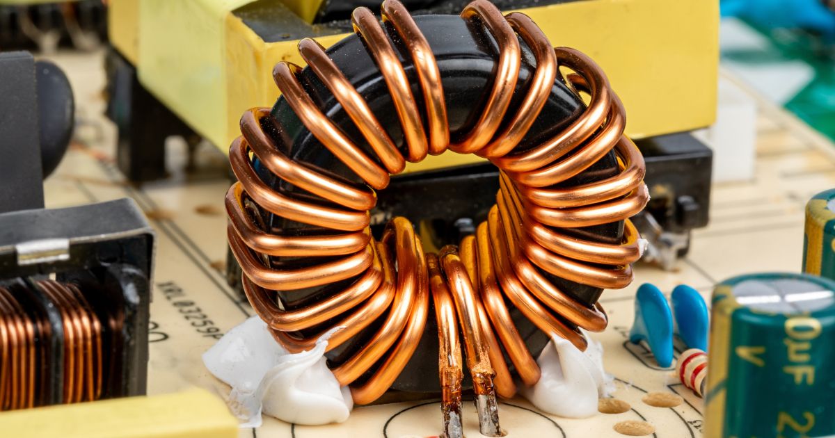
In this article, I’m going to guide you through the standard ferrite core selection and design process used in applications such as a DC-to-DC converter or a power filter inductor. The process involves a sequence of steps requiring the use of several data sheets and, should the ferrite core inductor design need to be gapped, some degree of iteration. These are the stages of ferrite core selection and inductor design we'll go through:
| Stage 1 | Stage 2 | Stage 3 | Stage 4 | Stage 5 | Stage 6 | Stage 7 |
| Target the core size | Study the ferrite materials | Choose the ferrite material | Calculate the number of turns | Calculate the required current | Calculate the flux density | Determine if a gap is needed |
Before proceeding, the implications of the decision to use ferrite cores rather than any other material need to be considered. Make sure this is the best material for your application before proceeding.
| Advantages of using a ferrite core inductor | Disadvantages of ferrite core inductors |
|
|
Target the core size (stage 1)
The design we are using as the basis of this article is aiming for an inductance of about 1 mH, and the ferrite material that will be considered is a planar type made by Ferroxcube. The part number is E38/8/25 and two halves are needed to make a full core set:

Highlighted in the red box is the core’s effective length (ℓe); this is an important value for calculating the peak flux density. It is the average travel distance of the magnetic flux when two core halves are brought together. It is shown using the blue line in the figure below:

On the right is how the core set and PCB will be constructed; The copper PCB tracks will form the coil loops, and we may have to stack several small PCBs to get the right number of turns. Another aim of this design is to keep the overall profile height as low as possible. Hence, we have targeted a planar core set.
Study and choose the ferrite material (stages 2 and 3)
The E38/8/25 core can be bought in several different ferrite materials. The common material types are 3C90 and 3F3. The next thing is to look into both these material types to see if one might be preferred over the other. The first comparison is the frequency response, i.e., how high a frequency is the ferrite material suitable for:

The solid lines show the material’s magnetic permeability (the ferrite “feel-good” factor). At 100 kHz, they both have a value of around 2000. This tells us how much better than fresh air they are at (a) concentrating the magnetic flux and (b) constraining it. Both are 2000 times better than air, and that is important. But there isn’t a big difference between the two at 100 kHz, and they both have reasonable performance up towards 1 MHz.
The dotted lines indicate the core material losses, and at 1 MHz, the 3F3 material is a little superior to 3C90.
The next comparison shows how much the magnetic permeability changes with core temperature:

Over a typical operating range of 0 °C to 100 °C, the 3F3 material would be the preferred choice. Not shown is another comparison that should be made, and that is the core saturation levels. However, I’ve not included it because both materials are pretty close, and it doesn’t influence the decision to go for 3F3 material.
Recap
We’ve targeted a core type called E38/8/25 (made by Ferroxcube), and we have investigated what materials it can be made from. Material 3C90 and 3F3 are both commonly available, and when looking at their material specifications, we’ve decided to go with 3F3 as it performs better.
We have had to look at three different data sheets to get this far; the datasheet for the core set E38/8/25 told us what materials it can be made from and, it also told us the critical parameter called effective length (ℓe). Then we looked at the datasheets for the two materials and made a side-by-side technical comparison.
Calculate the number of turns (stage 4)
We return to the E38/8/25 core data sheet and look for a number called AL (the inductance factor):

The relevant figure here is the 7250 number at the bottom left. It is said that for one copper winding turn, the inductance will be 7250 nH (7.25 μH). This is the value when using two identical planar core halves brought together. You should also note the associated value for the core’s magnetic permeability (𝜇e) is 1570. Originally, in the material specification, it was 2000; however, once it has been molded into a core, it will reduce slightly. The “e” in 𝜇e stands for “effective,” i.e. 𝜇e is called effective permeability.
Because ferrite materials concentrate the magnetic flux and (pretty much) ensure that all winding turns are coupled to each other, the relationship between the number of turns and inductance is, therefore:
L = AL . N2
Our target inductance is 1 mH, so we will need
Calculate the required current (stage 5)
We have a core set (and our core material), and we have now calculated the required number of turns, but what current do we need to flow, and will it cause problems? Too much current can lead to core saturation, so we need to avoid that, but we need to know about the application a little more to calculate the current. For this example, we’re assuming the application is a DC-to-DC converter using the ferrite core selection guide and windings as a DCM flyback transformer ferrite cores.
Because it’s a flyback circuit, we don’t need to analyze any secondary circuit aspects to calculate the primary current; we just need to know the maximum power delivered to the load and the operating frequency. So, let’s say the operating frequency is 100 kHz, and the power required by the load is 40 watts.
If we divide the load power by frequency, we get the energy in joules that the primary has to store and transfer to the secondary in each switching cycle. We must assume there will be some losses, so we will make the energy 10% higher to account for these. If we manipulate the “well-known” inductor energy formula, (E = ½ L ⋅I2), we can calculate the peak current needed to flow in the primary with the following equation:
Of course, if you have a different application circuit in mind for the wound component, then the current calculation may be more straightforward than that shown above. In either case, you still need to calculate the peak current to see if there might be a potential core saturation problem.
We calculated 0.918 amps for our target application, and we know that this current is the transformer ferrite core magnetization current for a flyback converter. Therefore, it could easily over-saturate the core.
Calculate the flux density (stage 6)
To calculate flux density, we need to use the peak current, the number of turns, and the value of effective length (ℓe) we found in stage 1 (52.4 mm for two E38/8/25 core halves). Do you recall this figure?

The peak current, number of turns, and ℓe all contribute to a value known as magnetic field strength, H:
If we multiply H by the magnetic permeability, we get the flux density, B. We know the magnetic permeability (𝜇e) is 1570 compared to air, and we know (from various sources) that air has an absolute permeability of 1.257 𝜇H per meter. Hence, we can calculate B as follows:
B = 210.2 ×1570 ×1.257 ×10-6 = 0.4148 teslas
This is the predicted peak flux density, and we know from the literature that it is too much for ferrite cores. Ferrite will heavily saturate around 0.4 teslas, so we have to slightly rethink what we are doing.
Determine if a gap is needed (stage 7)
The simple answer is yes, we need to reduce the predicted peak flux density. The good news is that we can buy the E38/8/25 core set already pre-gapped. Do you recall this data sheet extract from stage 4?

So, instead of picking two ungapped cores, we could choose one core with a gap and one ungapped core. This would produce the following core construction:

So, if we picked a core with a gap of 0.25 mm (250 𝜇m), the AL value has reduced to 1000, and this means that we need more turns to produce 1 mH inductance.
- From stage 4, we should now use 32 turns to get 1.024 mH.
- From stage 5, the peak current should be 0.927 amps (previously, it was 0.918 amps).
- From stage 6, H is now 566.1 ampere-turns per meter (previously it was 210.2 At/m)
Then, we can recalculate peak flux density using the value for the gapped magnetic permeability 𝜇e of 216.
B = 566.1 ×216 ×1.257 ×10-6 = 0.153 teslas
This shows the effect of merely adding a gap. We would tend to want a value below 0.2 teslas for our flyback converter, so this is a comfortable fit. Here’s what a simulation gives us (as a kind of sanity check):

The numbers tally reasonably well. The gapped core set with an H field of 566.1 has a simulated flux density of 129 mT, whereas the hand calculation arrived at 153 mT. For the ungapped 12-turn core set with an H field of 210.2, we get a simulated flux density of 413 mT (very close to the hand calculation of 414.8 mT).
Summary
Firstly, what is essential is that you use the correct design process when designing a transformer ferrite core or using a ferrite core inductor. Secondly, there is no substitution for real-world final testing. This is needed for any hand-made (or homespun) wound component. However, this article can only really show the process, and it is hoped that if you follow it, you get good results. If you gain some greater insights into designing and gapping a ferrite core inductor design along the way, then that’s a bonus.
Have more questions? Call an expert at Altium and discover how we can help you with your next PCB design.

