


Nucleo Shields Multi-Board Design

At a Glance
Learn how easy it is to create multi-board projects in this practical project article. Mark Harris covers why you would break larger boards into sub assemblies, and connection options between sub assembly boards.


In this article, we’re going to build a shield for an STMicroelectronics Nucleo development board, though as it is only using the Arduino compatible headers, it would be usable on any development board featuring Arduino-style headers. By prototyping on a development kit, we can prove our design without worrying about the implementation of the microcontroller, power, or communications.
This also allows us to determine real-world processor requirements our implementation has, by using a standard form factor we can switch between a large range of microcontrollers from various manufacturers without needing to create multiple boards. This can allow us to flesh out requirements and determine which microcontroller board deisgn is optimal for our application, allowing us to rapidly prototype to evaluate microcontrollers with a wide range of capabilities across a broad price range.
This however is not the only use for sub-boards in the electronics industry. Creating hardware with multiple boards is very common and can offer technical challenges to engineers working with them. Altium’s Multi-board capabilities help alleviate these challenges by giving engineers the tools to mate their hardware together in the design environment, confirming electrical signals and mechanical connectors are aligned and compatible before committing to ordering boards.
EnviroShield Project
For this article, we’re building a relatively simple weather station. It will feature a high-precision digital relative humidity/temperature sensor and a high-precision digital pressure sensor. We’ll also have an LCD display to show the current values. This shield would be perfect for accurately monitoring the environment within a home, lab, or industrial environment. If this board was placed on a development kit that has network connectivity (wired or wireless) it could easily store data in a database, or be monitored remotely.

As with my other projects, you’ll find the design files for this project on my GitHub. It’s open source, and free to use - however comes with no warranty or guarantee under the MIT license.
Why Multiple Boards?
As mentioned above, splitting your hardware into multiple boards is a common strategy to solve a wide range of challenges in designs. Managing the complexities of multiple interconnected boards may have put you off in the past, however as you’ll see with this project, Altium’s multi-board projects make life easy.
So why would you consider splitting a project into multiple boards?
Prototyping
During the early stages of a project, reducing engineering risk and focusing on the critical portions of a design can rapidly accelerate the design process. You can quickly try out alternative components, verify that component capabilities match your requirements, and rapidly have a proof of concept to demonstrate to stakeholders.
The EnviroShield project we’re building in this article falls into this category - we’re rapidly building an environmental sensor without having to worry about the host microcontroller board design or networking implementation. Using a low-cost development kit, and a relatively simple shield board we can quickly evaluate our sensor components and test our code while reducing the engineering risk of the board.
Space Saving
If your project has a large number of components and too little space, stacking boards can offer a lot of advantages. As electronics engineers, we typically think about horizontal space and rarely consider the vertical axis when it comes to design. The majority of components a typical circuit board holds are low profile. By utilizing ultra-low profile mating connectors and intelligent board shapes to work around larger components such as aluminum capacitors or connectors, you can double your board area with only a minor volume increase.
Isolation
There are often times in projects where you have two blocks of components you just don’t want on the same circuit board as each other. As an example, you might have some small signal precision sensor inputs you’re amplifying, yet have a high current driver or powerful radio in the same design. You might also have AC voltage coming onto the board, and don’t want it near your other components.
By physically separating schematic blocks that don’t necessarily co-exist well, you can reduce the risk of your design failing to perform as expected.
Modularity
While this project falls more toward the prototyping category, it is also a modular design. We could place our environmental sensor on a host board with networking capabilities, or use a simpler host board that keeps costs down. Whether you’re designing the host board, or a sub-board, by using a standardized electromechanical connection you can offer your customers future expansion to a device, or enhanced capabilities.
You’ll find this type of plugin modularity very common in power supplies, data collection hardware, and audio/video production equipment to name a few.
More?
We’ll talk more about reasons you might want to create surface-mounted sub-boards in our next multi-board article. We will focus further on modularity, certification, and cost reduction criteria for taking functionality to another board.
Board-to-Board Connectors
When designing a product that will have multiple circuit boards, you’re going to need a way to connect them together. While you could use a wire/cable assembly or flex to connect the boards, in this article we’re looking at boards closely mounted and directly connected. Direct connections are easy to manufacture from prototype volumes to large volume production - whereas custom cable harnesses are typically going to have a minimum volume requirement to be cost-effective.
Rectangular Header
In this example project, we’re using simple rectangular headers. The board could be assembled using breakaway pin headers or with the more typical (for an Arduino shield) long-tail female header. Rectangular headers come in a wide variety of pitches, lengths, rows, and position counts depending on your needs. They typically handle moderate amounts of the current well and have low resistance connections that hold together well.
Rectangular headers are readily available in both through-hole and surface mount variants.
Rectangular headers are often seen as a budget connection option, but when comparing the prices of rectangular headers to mezzanine connectors you may find that mezzanine connectors are more cost-effective per pin and take up a lot less space on your board.
Mezzanine
Mezzanine connectors are typically surface mounted with high pin counts and can be extremely low profile. Mezzanine connectors are perfect for a large number of signals in tightly integrated hardware, where assembled volume is critical. That being said, mezzanine connectors are readily available from 3 positions to many hundreds, with some very creative combinations of functions beyond basic pins. Some connectors offer dedicated pins for power which offer higher current or voltage ratings. Other connections may include RF jacks which can transfer RF signals efficiently from one board to another.
With pin pitches down to 0.3mm and mated heights as low as 0.6mm and up to tens of millimeters being well stocked, despite the current shortages, mezzanine connectors are my typical choice for interconnecting boards.
Backplane
If you’re building rack-based modules, DIN 41612 backplane connectors offer high pin counts and reliability in a standardized connector. You’ll also find Hard Metric (Hm) as an alternative standard offering similarly high pin counts. Finally, there are the ARINC-type backplane connectors, however, these robust connectors are highly targeted at aerospace and defense and priced accordingly.

Source: Harting DIN 41612 Backplane Connector at Digi-Key
Backplane connectors are typically going to be used for specialized applications such as modular equipment or systems in some form of the rack the boards slide into and probably won’t be your go-to connector style.
Card Edge/Edgeboard
If you need your board to plug into another one repeatedly and reliably, card edge connectors can offer a low-cost option. You’re probably most familiar with PCI-E cards such as for a computer graphics card, or RAM DIMMs on a computer motherboard, and while you can use these standards there are also more generic options available.
Tiny single-board computers are commonly available in SO-DIMM and MXM format. This allows you to shift the engineering complexity of the application processor and RAM into a sub-board. It is a great example of using a standardized connector for something other than its intended use.

Source: Amphenol MXM3.0 Connector
Generic connectors such as TE’s Standard Edge II series give you an option that won’t easily be confused with something that is a well-known standard.

Source: TE Standard Edge II Connector on Digi-Key
One major advantage of card edge connectors is that only the host board needs to have a connector mounted on it. The daughterboard will have contacts on one edge of the board that slot into the host board’s connector. This can reduce cost while providing a reliable connection, though typically using an edge board connector is not going to be a space-saving option.
Solder
When you don’t need the two boards to be separated at a later stage, and your primary goal is not to reduce volume, directly soldering one board to another is a viable option. Creating your own surface mount module is not difficult, and I’ll be covering how to, as well as the pros and cons of this approach in my next multi-board project article.
Preparing the Nucleo Board Design Files
I’m using an STMicroelectronics Nucleo-64 as my host board. They are low-cost development boards for prototyping with powerful processors and a wide range of peripherals. When you need more connectivity than simple Arduino headers, the full range of pins on the device is available through the auxiliary Morpho connectors. I downloaded the Altium design files from ST to form a starting point for this multi-board assembly.
Ideally, I would just need to add a single parameter to each of the Arduino connectors to indicate they are for a multi-board interconnect. However, my library has a full Arduino header as a single component, which lets me add the Schmartboard Arduino header pack to my board as a single BOM line. This also ensures that all the headers are laid out correctly both mechanically and electrically. The ST Nucleo shield board has separate headers for each Arduino connector, and a multi board computer is one-to-one. Therefore, I replaced the headers in the Nucleo shield board design for the project with my own library component for the Arduino headers.

STMicroelectronics Nucleo-64 board with replaced Arduino headers.
Once that is done, all that is needed is to add the parameter “System” with the value “connector” and the Nucleo shield board is set to go. It’s very painless and quick to prepare an existing board for a multi-board assembly.
Building the Environmental Sensor Shield
For this project, I want to have a relatively simple indoor weather station that will give me relative humidity, temperature, and pressure. By building it on a dev kit, I can prove the board design for project and performance before moving on to a more robust fully integrated design in the next project article.
For the sensors, I’ve selected TE’s excellent HTU21D series sensors, which oddly have the part number HPP845E031. They offer excellent resolution and precision and importantly for me, are rated all the way to 100% humidity. Many humidity sensors will max out below 100%, some as low as 80%.

Relative Humidity/Temperature Sensor Schematic
I was originally planning to use TE’s MS5611 (previously Measurement Specialties) pressure sensor, but for my application, the precision/resolution is beyond what I need, and I couldn’t justify the price. Instead, I’m using the MS5607 which is pin compatible, so I can switch to the other option if I want to go really over the top in the future.

Pressure Sensor Schematic
I also have a relatively small Newhaven Displays graphic LCD with a white backlight on the board. This will allow me to get more creative with the display than a character LCD. I have a button on the board that I can press to enable the backlight, so it isn’t on all the time. The button could also be used to cycle through various displays as well if I want to program that feature in the future.

Newhaven Display Schematic
Preparing the Project for Multi-board Use
As with the host board, we need to tell Altium Designer which connectors will be used for our multi-board interconnect. Once again, this is as simple as selecting the Arduino header schematic symbol on our schematic sheet and adding a new parameter in the properties panel.

Add Parameter to Connector Properties
Add the property “System” with the value “Connector”.

System Property Added
With that simple addition, everything is prepared for multi board computer use.
Temperature Sensor Considerations
The only non-routine portion of this circuit board is the considerations that should be taken for the temperature sensors. As I mentioned in my “Temperature Sensor Project” series, a thermal break between the sensor and the rest of your board can help improve the accuracy of the reading - assuming you want to measure ambient temperature rather than the board’s temperature.

Thermal Isolation Slots
On this board, I’m isolating the temperature sensor and placing it against the bottom edge of the board. My plan is to mount this board vertically, with the USB cable for the dev board sticking up vertically. Any heat output from the boards will cause convection currents to bring ambient temperature air over the sensor.
Creating the Multi-Board Assembly
With our host board and shield completed, we can move on to creating the multi-board assembly.
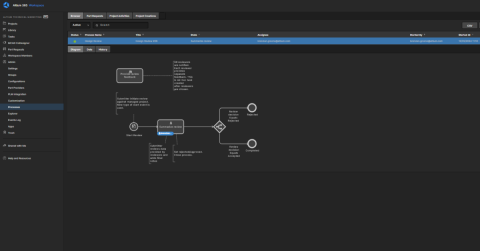
The first step is to create a new project, however, rather than selecting PCB on the project creation screen, we select Multi board computer.

Creating Multi-board Project
We then create a new multi-board schematic.

New Multi-board Schematic
With the new schematic sheet saved, we add two modules - one for each board, then assign the boards to them from the properties window. I also set the title for each module to make it easier to identify which module is which.

Multi-board Schematic Modules
Once that is done, we can go to Design -> Import From Child Projects, which will add ports for each connector we added the System=Connector parameter to.

Import From Child Projects
To visually show the mating direction, I set the Nucleo board connector to be female, and the shield to be male.
For this board, we are going to be directly joining the boards together with their connectors, so we can add a direct connection between the connectors.

Adding a Direct Connection
This completes the multi-board schematic, as Altium has automatically assigned all of the connections between the two boards.

Completed Multi-board Schematic
Now we can add a new multi-board assembly to the project, once it’s open, make sure to immediately save it.
With the multi-board assembly saved we can go to Design -> Update Assembly which may take some time depending on your computer’s specifications and the complexity of your projects.

Updating Assembly Engineering Change Order
Once complete, you will have each of your boards within the 3d PCB workspace. We can use the mating tools to join the connectors together.
First select a pin on the Arduino connector on the shield, making sure the reference point is in the center of the pin, and on the plane where the connectors will meet.

Selecting Mate on EnviroShield
Then select the hole on the Nucleo board, making sure the reference point is in the centre of the hole.

Selecting Mate on Nucleo Board
For me, the pins connected correctly but the orientation is not ideal. In the Multi-board Assembly panel (accessed from the Panels button in the bottom right corner of Altium Designer, if it is not already open), you can view the mates.

Multi-board Assembly Mate Orientation
I simply had to change the orientation of the mate to 180 degrees and everything was properly connected.

Completed Multi-board Assembly
Collecting Interesting Data
One very interesting piece of unexpected data that my prototype unit collected was the shockwave from the very large eruption of the Hunga Tonga–Hunga Haʻapai volcano in Tonga on the 14th of January 2022. Despite the fact my weather station is over 15,500km away from Tonga, there is a visible pulse in my pressure data. I’m only storing average data every 30 mins despite reporting data more frequently, yet the peak pressure of the shockfront and low pressure behind the shockwave is still clearly visible. The peak pulse is much lower than government-run sensors across Europe, however, the sensor was inside a building with meter-thick stone walls, rather than being outside.

It’s data such as this which really cements my love of building data collection and sensor hardware!
Outcome
By building a multi-board assembly within Altium Designer, I was able to ensure all my signals are electrically and mechanically aligned between the two boards. I can also check the boards fit together properly by using the Tools -> Check Collisions to make sure I won’t have any unexpected surprises once I have physical hardware in my hands. Multi-board projects look as though they might be complex to work with, however, Altium’s tools make the job easy. Building your multi-board assemblies in Altium saves you time by allowing verification in the digital world, rather than finding your assembly has issues in the real world when assembling prototypes.
Can multi-board assemblies save you time, and increase your productivity? Talk to an expert at Altium now to find out how.
About Author
Related Resources
Related Technical Documentation
Table of Contents
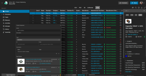
Design to Release, Without the Friction
- Keep reviews tied to the right version
- Reduce handoff confusion and rework
- Spot sourcing and release risk earlier
- Work solo, share when needed
Get Started
Thank you, you are now subscribed to updates.

