



Rigid-Flex Panelization: What the Fabricator Needs From the Designer

At a Glance
Learn what fabricators need from rigid-flex panelization. Get tips on stiffener support, breakaway tabs, and nesting to protect yield before layout is final.


Creating the panelization for a rigid printed circuit board is fairly straightforward. What is the preferred array size and how many PCB’s can fit in that space, along with the necessary tooling holes. Panelizing a flexible circuit is similar, but often with more unusual shapes to work with. In both cases, material utilization is the primary consideration. Rigid-flex constructions are not as simple. On a rigid-flex board, a bad panel layout can cost yield, cause damage during depanelization, or leave the flex sections without the support they need to survive handling before the boards ever reach assembly. Upfront knowledge of the fabrication process itself and discussion with both the fabricator and assembler prior to creating the array is critical.
It can be tempting to first think of material utilization as key in rigid flex layout. The reality is that this specialized construction has many factors that impact yield. An “L” shaped design can reverse nest on the panel and significantly improve material utilization only to learn later that the orientation of the flex tail is critical during processing and that strategy is impacting yield.
Key Takeaways
- Rigid-flex panelization carries risks that rigid-only panels don't, because flex regions have to survive handling and process steps beyond the final part outline.
- Stiffener support, breakaway tab placement, and nesting orientation relative to bend direction all affect yield and can cause field-level cracking if done wrong.
- Panelization issues caught late usually force a choice between a costly rework and accepting lower yield.
- Bringing panelization into the conversation during layout, not after the design is finished, is the cheapest way to avoid both.
Why Rigid-Flex Panelization Isn't Just Rigid Panelization With Extra Steps
A rigid board panel is largely a nesting problem: how many boards fit, how much material is wasted, where the tooling holes go. Rigid-flex adds a second set of constraints on top of that, because the flex regions in the design have to survive everything the panel goes through between lamination and final singulation.
That means we're thinking about panelization from the very first layout review, not after the design is finished. Where do the flex sections sit relative to the panel edges? Is there enough rigid material surrounding each flex area to support it through drilling, plating, and routing? Are the flex regions oriented so the bend direction doesn't fight the panel's handling direction during assembly?
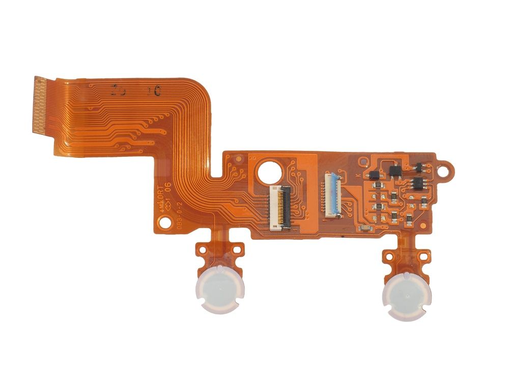
What Fabricators are Looking For
A few things that consistently separate a rigid-flex panel that runs well from one that generates scrap:
- Adequate stiffener or rigid support around flex regions during panelization, not just in the final part. A flex area that's unsupported through the panel process is exposed to stress it was never designed to handle.
- Breakaway tab placement that doesn't stress the flex layers. Tabs positioned too close to a bend area, or oriented so depanelization forces travel through the flex, are a common cause of hairline cracking that doesn't show up until the board is flexed in the field.
- Nesting orientation that respects the flex bend direction. Two identical boards nested in opposite orientations on the same panel can behave differently through the same process steps.
- Enough clearance between adjacent parts and panel rails to account for the flex material's tendency to shift slightly during lamination, which rigid material doesn't do to the same degree.
None of this is visible if you're only looking at the single-board outline. It only shows up once the design is placed on the actual panel and runs through the process as a set.
The Cost of Getting This Wrong Late
Panelization decisions made late, or left entirely to the fabricator without design input, tend to surface as problems well after the design is otherwise finished. A panel layout that wasn't reviewed against the flex geometry can force a choice between reworking the panel (schedule cost) or running it as-is and accepting lower yield (unit cost). Neither of those is a good trade if it could have been caught earlier in the process.
This is also where communication between designer and fabricator earns its keep. A five-minute conversation about panel orientation before the design is finalized is a lot cheaper than a first-article failure traced back to a breakaway tab that was never going to hold up.
Panelization Is a Design Conversation, Not a Fabrication Afterthought
The boards that panelize cleanly are usually the ones where the designer understood, even at a high level, how the panel would be built and handled before the layout was locked in. That doesn't mean a designer needs to spec the panel themselves. It means treating panelization as a question worth asking early, the same way stack-up or material selection gets asked early, instead of something that only comes up if there's a problem.

About Author
Related Resources
Related Technical Documentation
Table of Contents
Solutions for Every Role and Team
- Discover and evaluate design options earlier
- Develop in one shared workspace
- Scale with control and compliance
- Connect every stage of hardware development
Learn More
Thank you, you are now subscribed to updates.