


Advantages of Using Draftsman to Create a PCB Assembly Drawing

At a Glance
You don't need to use a mechanical drawing application to create your PCB assembly drawing. Instead, you can use Draftsman, an easy-to-use feature in Altium.


Standard assembly drawing applications are not designed for creating drawings specifically for electronic assemblies. Printed circuit boards have complex features and placements that are not easy to render in most drafting applications, so significant time may be required to create these drawings. Something faster is needed to quickly create a production-grade drawing your assembly house can use to build your PCB.
The Draftsman feature in Altium offers an elegant, yet powerful solution to make these tasks easier. You can quickly create an assembly drawing with specific views of the PCB, including selected component information, dimensions, title blocks, and much more. Your assembler will have a clear understanding of where components must be mounted, and it's easy for the inspection service to verify this.
What Goes Into a PCB Assembly Drawing?
Every assembly drawing needs to have some basic information that shows the location and orientation of major components on the PCB. Some of the primary information required to produce an assembly drawing includes:
- An assembly drawing with the placement of major components
- Top, front, and side view of the PCBA
- Fiducials and/or mounting holes clearly visible
- A set of PCB assembly notes
- Callouts with any important assembly information
- Portions of the BOM that require any special assembly instructions
- Title block with company and artist information
The goal of an assembly drawing is to help the assembler define the orientation of the bare board for assembly equipment, which will then be used to program automated assembly equipment. With an assembly drawing that shows the locations of the major components, there is much less room for error
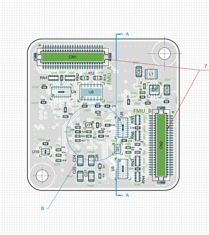
To show some of the important information found in an assembly drawing, we created an example Draftsman document that highlights the available features and functionality. In the drawing below, we've included all the information an assembler might need to see to ensure the board is assembled and inspected correctly. Download the assembly drawing pdf for easy and effective preparation.

When you’re ready to streamline your design and production workflow, use the world-class CAD features and automated PCB assembly drawing tools in Altium. You and your team can create advanced designs and quickly prepare them for manufacturing while staying productive and efficient. When it's time to release your designs to production, use the complete set of release management features in Altium to collaborate with your manufacturer. Everything you need to design and produce advanced electronics can be found in one software package.

About Author
Related Resources
Related Technical Documentation
Table of Contents
Design to Release, Without the Friction
- Keep reviews tied to the right version
- Reduce handoff confusion and rework
- Spot sourcing and release risk earlier
- Work solo, share when needed
Get Started
Thank you, you are now subscribed to updates.

