


Antenna Impedance Matching Calculator with Altium Designer


Impedance matching plays a critical role in high speed, high frequency, and wireless PCBs. Building a PCB with strong wireless communication capabilities requires impedance matching your antenna to its receiver/transceiver using one of many termination schemes, especially if you opt to print your own antenna on your PCB. When you use design software with the best signal simulation and analysis tools, you can easily identify the best termination scheme and components to use for your antenna. Only Altium Designer includes the tools you need to design your own antenna and verify that it is impedance matched.
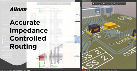
ALTIUM DESIGNER
A PCB design package with the best design and signal integrity tools in a single program.
Unless you’ve worked with high speed, high frequency, RF, or other wireless technologies, you may not be familiar with transmission line impedance matching techniques or the networks that are used to define impedance values in your board. Matching networks are arrangements of components that match the impedance of a source and load. The goal is to prevent signal reflections at the load, ensuring that signal strength is not lost upon entering your receiver/transceiver. For example, when the signal transmission line trace has the same order as the wavelength of the signal, impedances must match or the signal will reflect and overheat the PCB.
Similar to the termination schemes that are typically used to impedance match traces to sources and loads on an interconnect, termination networks for antennas can provide filtration as well as matching to a specific impedance value. If you are working in an environment that presents noise at a specific frequency, or you want to isolate your antenna network from specific noise sources elsewhere on your board, picking the right network and component values is critical for ensuring signal integrity.
Using an Antenna Impedance Matching Calculator
An antenna tuner doesn’t change the antenna itself so much as changes its impedance to match the transmission line source, for example changing the impedance from 50 ohm to 55. If you look through search engine results, you’ll find plenty of links to calculators that can help you properly match the antenna tuner load impedance with your trace. These calculators will help you build an impedance matching network for a known source and load impedance values without needing to develop your own smith chart and ensure you can avoid reflection coefficients. The best calculators will allow you to choose from several different networks to impedance match your antenna and will show you the values of the inductors and capacitors you need to use in your matching network.
Each impedance matching network will provide some additional benefits like filtration. Impedance matching networks for antennas are designed to pull-up or pull-down the impedance of the load, as well as provide some filtration to the analog signal in the network. Learning to select and use the proper network requires carefully perusing datasheets for antennas and receivers/transceivers in your network.
Impedance Matching For Chip and Printed Antenna
When with an impedance matching calculator, you need to consider whether you will be working with a chip antenna, printed antenna, or an external antenna, such as a patch or rubber ducky antenna. Printed antennas will have impedance values that depend on the geometry of the antenna, while chip and other pre-built antennas generally have a specific impedance value at the required frequency.
Many manufacturers offer calculators for antenna matching networks online, but many of these antenna impedance matching calculators are limited in their capabilities. They may only offer a small number of networks (usually one), severely limiting the capabilities you can consider in your design. Interpreting the results from these calculators also takes some experience. If you input the wrong values into these calculators, they may require you to use components with negative capacitance or inductance, indicating an obvious user error.
Instead of taking your chances with a calculator, it is much easier to design a matching network when you use a signal integrity tool that iteratively calculates the component values you need in your network. These tools will iterate through a number of component options and show you the reflected signal you would see in your network. This takes the guesswork and internet searching out of impedance matching.
- Should you use a chip or printed trace antenna? There are plenty of trade-offs to consider when designing your next wireless device. Learn about the trade-offs between chip and printed trace antennas.
- Printed antennas require a number of design issues that go beyond impedance matching. Learn more about designing your own printed antenna.
- Termination methods for traces and for impedance matching networks are useful outside of antenna design. Learn more about termination methods in high-speed and high-frequency designs.

Layout and schematic unification in Altium Designer
Printing Your Own Antenna
If commercially available chip or patch antennas don’t meet your needs, you can opt to print your own antenna. The impedance of your antenna will depend on a number of factors, but you can easily impedance match your antenna using the signal integrity tools mentioned above. Once you calculate the impedance of your antenna, you can incorporate it into the appropriate impedance matching network, or you can use an antenna impedance matching calculator from a component distributor.
CAD and Verification Tools for Antenna Design
Your CAD tools should make it easy to define copper pour regions for printed antennas. Any printed element on your board, as well as the components you include in your matching network, must comply with standard design rules. A powerful design rule editor allows you to define design constraints and new design rules that are specific to your application.
- Signal integrity simulations are critical for ensuring your antenna is properly designed and matched to the rest of your board. Antenna design is much easier when you include signal analysis as part of your overall design process.
Learn more about incorporating signal integrity simulations into your design process.
- Antenna design requires proper ground plane design and placement. Learn more about ground plane design in your PCB.
- Any antenna or matching network must work within your design rules. The automatic design rules checking features help you quickly identify and solve problems from design rule violations.

Defining copper pour areas in Altium Designer
Design and Signal Analysis in a Single Package
Other design platforms claim to place all of your critical design and simulation features into a unified environment, but they still force you to switch between programs when accessing basic design features. Some programs will block access to these features behind a paywall, leaving you feeling bamboozled. Only Altium Designer places all the critical PCB design features you need in a single package with a consistent workflow.
Get Access to All the Critical Design Tools You Need in Altium Designer
When all your design tools are present in a single interface, you can easily access any design feature you need when designing your antenna. Using an antenna impedance matching calculator is a good way to get started with your design, and the design tools in Altium Designer will take you to the finish line. You can implement any impedance matching network for your device and quickly verify its effectiveness in Altium Designer.
- Altium Designer places all your critical design, deliverable generation, and management tools in a single program with an intuitive interface. Learn more about the unified design environment in Altium Designer.
- The rules-driven design engine ensures that all of your design features work together and helps you spot errors during the design phase. Learn more about Altium Designer’s rules-driven design engine.
- As you move through the design phase of your next system, you’ll need to check your design against standard design rules during schematic capture and as you layout your board. Learn more about ERC verification in Altium Designer.
With Altium Designer, you won’t have to rely on an external calculator to size a printed antenna or design an impedance matching network. The signal integrity and analysis tools will help you ensure that your antenna remains impedance matched at the desired frequency. These tools seamlessly integrate with the rest of your design tools in a single program.
The unified design environment offers all your critical design and analysis features in one place. If you need help getting started or you are just looking for useful design tips, Altium gives you all the resources you need to come up to speed quickly. From the AltiumLive forum to an extensive knowledge base, webinars and podcasts, and useful feature tutorials, Altium gives you the features you need to be successful.
No other design platform includes critical design, simulation, verification, collaboration, and management tools in a single program. Rather than switching between design programs just to access basic design features, you should try using the only PCB design platform that operates with a unified environment. Altium Designer makes it easy to implement the design strategy you need for your next wireless device.

About Author
Related Resources
Related Technical Documentation
Table of Contents
Design to Release, Without the Friction
- Keep reviews tied to the right version
- Reduce handoff confusion and rework
- Spot sourcing and release risk earlier
- Work solo, share when needed
Get Started
Thank you, you are now subscribed to updates.


