


A Review of PCB Thermal Resistance Management with Thermal Vias


Design of PCBs and thermal management are intimately linked as thermal problems are known to significantly reduce the useful lifetime of a circuit board and components. Heat that is generated in a circuit board by active and passive components tends to be confined near the components, leading to a high-temperature increase due to the low thermal conductivity of most circuit board substrates. Frequent cycling of a circuit board and components between high and low temperatures will reduce the longevity of your system and can lead to premature failure of components or copper conductors.
Any designer should consider how to manage heat generated from their components using a combination of strategies. Among these different strategies, designers can make use of a thermal pad and heat sink on each active component, creative use of copper planes on interior layers, substrate materials with high thermal conductivity, and thermal vias near active components that dissipate high power. Strategic placement of components is also important for preventing formation of hot spots in your printed circuit board.
Thanks to the design and analysis tools in Altium Designer, you can devise a strategy that will help keep the temperature of your board within acceptable limits, despite the high thermal resistance of most PCB substrate materials. The PCB layout tools allow you to design your board with thermal vias, passive and active cooling measures, and substrates with high thermal conductivity and custom stackup.
ALTIUM DESIGNER
A unified PCB design platform that integrates advanced PCB layout features with comprehensive via and pad design features.
The components on any circuit board will generate some heat during operation, and the proactive designer will take steps to combat excessive temperature rise during operation. If you’ve ever seen an overclocked gaming PC, then you’re familiar with the massive cooling fans and even liquid cooling systems used to remove heat from graphics cards and processors. Most likely, your PCB won’t need such extreme thermal dissipation measures. However, you should consider how to remove heat from your components and produce an even temperature distribution throughout your board.
The high thermal resistance of many circuit board substrates can cause hot spots to form near active components. These hot spots tend to accumulate near active components that generate a significant amount of heat. Among the different methods for combating temperature rise in a PCB, thermal vias are particularly useful for transporting heat away from active components and into an internal layer of your stackup.
Placing thermal vias below a pad with a die-attached paddle with the right number density is one method to transport heat into an inner board layer. You will see the best results if you optimize the number and arrangement of thermal vias below the component in question. When combined with other cooling methods, such as the use of a heat sink and thermal pad on each active component, and some active cooling measures, you’ll be able to keep the temperature of your components below their maximum rated values and extend the lifetime of your circuit board.
What are Thermal Vias?
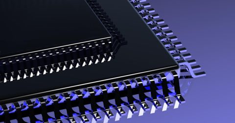
As many active components, such as devices for power electronics, high-speed processors, and high-frequency components, generate significant heat during operation, these devices require some thermal dissipation method to keep their operating temperature below the rated maximum. Thermal vias are simply vias placed below a component that spans through a stackup. These vias can connect to the ground plane in the stackup in order to transfer heat to an inner layer, where heat then conducts through the ground layer to the rest of the board.
Thermal vias can be placed as through-hole vias so that they provide thermal dissipation throughout the stackup. The annular ring of these thermal vias should be visible through the solder mask on the surface layer below the target component. They can be soldered to the die-attached paddle to provide uniform thermal conductivity throughout the structure. Filling these vias with an epoxy or plating them is also a good idea as this prevents solder from wicking through to the back side of the board. If you examine the temperature distribution throughout the board, you’ll find that the temperature distribution in the surface and inner layer spreads out as you move away from a thermal via.

Heat transport away from thermal vias into the circuit board substrate
Arrangement of Thermal Vias Beneath an SMD Component
Many components, such as components in QFP packages, include a die-attached paddle on the bottom of the component, and thermal vias should be arranged in an appropriate pattern beneath the component. Placing the right number of thermal vias with the appropriate pitch between them will optimize the effective thermal conductivity of the structure, allowing the maximum amount of heat to be transported into the substrate and bringing the temperature closer to the ambient temperature in the environment. In general, you should opt for more thermal vias while staying within your manufacturing budget.

Example spacing of thermal vias on a circuit board
As many printed circuit boards are designed on an FR4 substrate, the high thermal resistance of this substrate material requires some type of thermal dissipation method to reduce the temperature of the board. Designers should consider combining thermal vias with other thermal dissipation methods to bring the substrate and component temperature to an acceptable level. This is especially important if your board will be repeatedly cycled between high and low temperatures.
- Thermal vias are just one part of a larger thermal management strategy for your PCB. You should include other heat dissipation methods, like a heat sink, thermal pad or paste, and cooling fans if thermal vias do not dissipate enough heat to an inner layer. Learn more about devising a thermal management strategy for your PCB.
- Each via in your PCB will affect your manufacturing budget, and you should carefully consider the PCB manufacturing process and budget when placing thermal vias.
Learn more about the circuit board manufacturing and assembly process.
- Just like other copper conductors in your PCB, thermal vias should be placed in accordance with your design rules and constraints.
Learn more about using design rule checks in your PCB design software.

Via, pad, and polygon design rules in Altium Designer
Your Substrate, Thermal Vias, and Heat Transfer
Even if you use thermal vias, you cannot guarantee that your board’s temperature will drop to a sufficiently low value. This is particularly true when your board is deployed in an environment with higher temperature, or in a portion of your system that will reach a higher temperature. While your board is in operation, the thermal gradient between your components and the environment will be lower, which will reduce the rate of heat transfer between hot and cold regions.
This is where using a substrate with high thermal conductivity is useful for quickly transporting heat away from active components. Ceramics are one of the best choices of substrate materials with high thermal conductivity. Another option is to use a metal core PCB; the thick copper core will provide significant thermal dissipation compared to a standard FR4 stackup. When combined with thermal vias, your substrate and stackup will help heat easily move laterally through your board, leading to a more uniform equilibrium temperature during operation. This leads to more uniform thermal expansion of your PCB, which causes internal stress to be less concentrated in different copper conductors in your system.
Other Thermal Management Methods
Other thermal management methods in your PCB can ensure the temperature of your board comes closer to the ambient temperature. These methods include attaching a heat sink to high-speed processors and other important components. A thermal pad on a heat sink helps provide a high thermal conductivity path for heat away from a component. If you have a large number of high-power components on your board, you may have no choice but to add fans to your design to remove heat from important components.
Your substrate material and your layer stack should also be designed with an eye towards heat transport away from the surface layer of your circuit board. The high thermal conductivity of copper in an interior layer of your PCB will easily transport heat away from thermal vias and towards the edges of the PCB. Your component arrangement is also quite important. Components that generate the most heat should be placed closer to the center of the board rather than at an edge as this will allow heat to dissipate over a larger area in your PCB.
- Your thermal vias should be designed to comply with IPC 2152 standards on thermal performance. Learn more about designing to comply with IPC 2152 guidelines.
- There are plenty of passive heat dissipation methods you can use to control the temperature of your PCB.
Learn more about passive thermal management techniques for your circuit board.
- An alternative substrate material is an excellent choice for transferring heat from hot to cold regions in your board and quickly dissipating it into the environment.
Learn more about working with alternative substrate materials.

Your substrate material and stackup will determine the thermal resistance in your board
Working with Thermal Via Design Software
Thermal via design software uses CAD tools to define standard geometry for your vias and their span throughout your layer stack. With the right circuit board layout tools, you can design the geometry and arrangement of your thermal vias in order to create a comprehensive thermal management strategy. The best software for designing thermal vias also includes stackup design features. This allows you to define internal copper layers that will help conduct heat throughout your PCB. These tools should be accessible alongside your other important routing and layout features, providing a complete solution in a single platform.
Complete Thermal Via Design and Layout in Altium Designer
With Altium Designer’s comprehensive stackup and thermal via features, you can easily create your layer stack, thermal vias, and layout in a single program. Altium Designer’s CAD tools are accessible alongside a complete set of simulation and production planning features.
- The integrated design environment in Altium Designer provides all the CAD tools you need in a single application. You’ll have access to important thermal via design and layout features in a single program. Learn more about unified design in Altium Designer.
- Working with rules-driven circuit board design software allows you to define important design rules and constraints for your board. This helps ensure functionality and manufacturability. Learn more about Altium Designers’ rules-driven design engine.
- With Altium Designer’s materials stackup library, you can choose from a large set of standard substrate materials with high or low thermal conductivity and various electrical properties. Learn more about Altium Designer’s materials stackup library.
The CAD tools and management features in Altium Designer are ideal for design of thermal vias, component layout, and placement of active and passive cooling measures to support heat transfer throughout your system. You’ll be able to define your via layout and manufacturing requirements as design rules and constraints. You’ll also have access to a set of powerful simulation and analysis features in a single application. When you add the material stackup library and extensive component libraries, you have all the features you need to design circuit boards with a powerful thermal management strategy and bring them to production.
Only Altium offers you a huge set of resources for printed circuit design. You’ll have access to the AltiumLive forum, webinars and podcasts with industry experts, design tutorials, and an extensive knowledge base with plenty of design tips. No other PCB design software company gives you this level of support. Instead of working with printed circuit design platforms that separate your important design features in different applications, it’s time to take an integrated approach to design and layout. It’s time to make the switch to Altium Designer.

About Author
Related Resources
Related Technical Documentation
Table of Contents
Design to Release, Without the Friction
- Keep reviews tied to the right version
- Reduce handoff confusion and rework
- Spot sourcing and release risk earlier
- Work solo, share when needed
Get Started
Thank you, you are now subscribed to updates.