





Three Ways To Simplify PCB Output Generation With Altium Designer


Manufacturing output errors often result from inconsistencies between files that appear correct individually. For example, a Gerber package may describe the revised board while its drill drawing describes an earlier hole pattern. In another common instance, a BOM may contain the correct components but represent a different assembly variant from the placement file. The manufacturer then has to resolve which documents define the intended build.
Ultimately, it comes back to the designer to determine which output file set is correct. The safest approach to take is not to generate individual outputs, it is to recreate the entire output package each time the design or requirements change. Altium Designer’s Output Job files feature will preserve the configuration used to generate that data so that the exported files can be repeatedly regenerated as needed, and always with the same settings.
Fabrication and Assembly Data Requirements
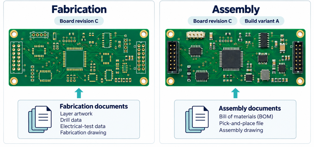
PCB manufacturers expect a defined set of data before they will quote or build a board. Fabrication relies on layer artwork in Gerber, ODB++, or IPC-2581, NC drill data, an IPC-D-356A netlist for electrical test, a testpoint report, and a fabrication drawing with notes covering materials, stackup, finishes, and impedance. Assembly relies on three deliverables that drive sourcing through final inspection:
- A complete BOM with manufacturer part numbers, reference designators, quantities, and approved alternates
- A pick-and-place file defining component locations and orientation for automated placement
- An assembly drawing with notes covering soldering, inspection, handling, and compliance requirements
Manufacturing Format Selection
As I’ve noted in other articles, Gerber files have become a de facto standard file format and they are universally supported by PCB manufacturers. Gerber RS-274X supports an established artwork-based process, while Gerber X2, X3, ODB++ and IPC-2581 carry more manufacturing information within a structured package. Not all suppliers will accept ODB++ or IPC-2581, and manufacturers will generally list the approved file formats they will accept on their website or in a capabilities statement.
Format | Fabricator acceptance | Complete Dataset | Revision traceability |
Gerber RS-274X | Confirm layer and drill conventions | Artwork supplemented by drill data, stackup, and manufacturing notes | Revision changes require regenerating all files, even if only one layer changes |
ODB++ | Fabricator must confirm database import support | Structured manufacturing database with some related design information | Complete database retained as one identified release |
IPC-2581 | Based on whether the file revision is supported | XML package that can include artwork, stackup, connectivity, components, and notes | Exported file retained with its source release |
The final aspect that is not always included in any of the above export formats is a master fabrication and assembly drawing. These drawings can be constructed in mechanical layers in the PCB layout file, but this is not a universal practice. Most of the master drawings I have created have been in an external tool, like commercial drafting software or in Altium Draftsman. This additional document should be provided to the fabricator because it provides the complete information about what they are being asked to build, and the information in this drawing cannot be applied in any other way in a PCB document.
Using Batch Output Generation in Altium Designer
Configure Output Job Files Once
An Output Job file captures every export setting for fabrication, assembly, and documentation in a single configuration. You can define Gerber RS-274X artwork, NC drill data, pick-and-place files, and documentation outputs within one OutJob file, each with its own format and layer selections. The configuration becomes part of the project, so the same output definitions move with the design through every revision.
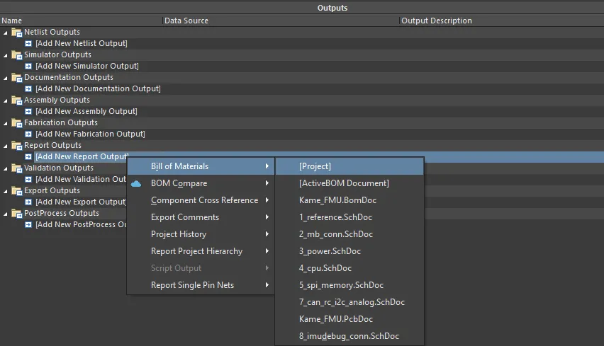
Once established, it removes the manual step-by-step export that introduces mismatched origins, missing layers, and stale drill data. Draftsman assembly and fabrication drawings can be added as documentation outputs alongside the fabrication files, and a PDF3D can be included as a visual sanity check for the assembly team.
Regenerate the Full Package on Every Change
Rather than exporting individual files when a layer changes, run the batch output to recreate the entire package. A single OutJob file can hold multiple enabled options for different sets of manufacturing documentation, so one run produces Gerber artwork, drill data, pick-and-place files, and drawings together.
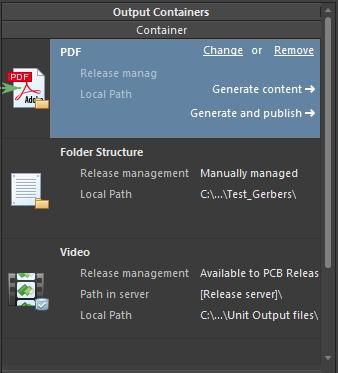
This keeps artwork, drill data, BOM, and placement data aligned to the same revision and prevents the variant mismatches that force the manufacturer to guess which documents define the build. Because the OutJob preserves the configuration, you can regenerate manufacturing deliverables whenever the design or requirements change and always get the same settings.
Release the Entire Design + Production Package
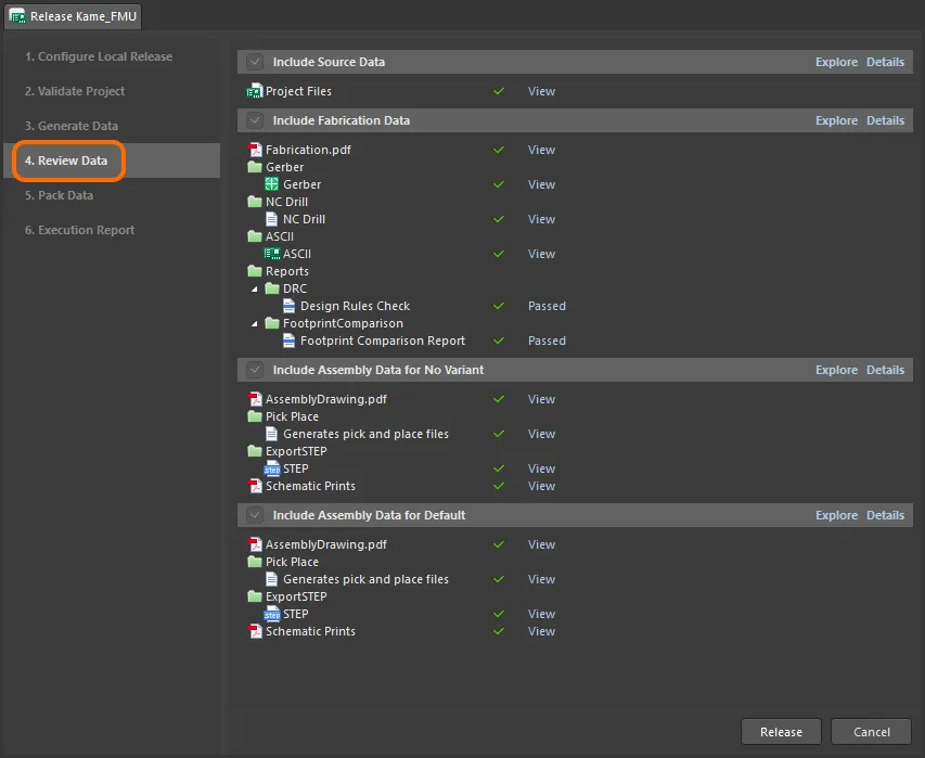
Batch generation ties the exported deliverables to a specific design release. The Project Releaser builds the package from the configured output generators and preserves it as a release artifact, and the Altium 365 platform lets you share and collaborate on that package with your fabrication and assembly vendors. The complete set carries consistent revision traceability, so fabrication and assembly data always reference the same source, and any regenerated output reproduces the identical configuration.
Incomplete Packages = Manufacturing Delays
If you forget to include layers in your exports, if files are missing, or the bare PCB build specifications are not provided in your outputs (i.e., you don’t have a fab drawing), don’t be surprised when your order is not approved for production. The result is a stream of technical questions to your email and delays in the production start date.
There are several discrepancies which are quite common, even among experienced designers:
- Missing solder mask layers, board profile, or fabrication notes
- Unclear drill units, coordinate format, origin, or plating type
- Origins defined at different locations in different files
- Incomplete stackup, material, or impedance requirements
- BOM entries without manufacturer part numbers or approved alternatives
Review of the exported package should establish agreement between artwork, drills, drawings, and component data. This catches errors that a layout check cannot reveal, including a correct design exported with an incorrect configuration. A repeatable output process preserves established settings; a coordinated release review establishes whether those settings produced the intended manufacturing package.
To learn more about manufacturing file outputs in Altium Designer, watch the video below.
Whether you need to build reliable power electronics or advanced digital systems, use Altium’s complete set of PCB design features and world-class CAD tools. Altium provides the world’s premier electronic product development platform, complete with the industry’s best PCB design tools and cross-disciplinary collaboration features for advanced design teams. Contact an expert at Altium today!
Frequently Asked Questions
Is there a way to create multiple PCB output file types as a batch?
Yes. An Output Job file in Altium Designer can group Gerber files, NC drill files, BOMs, placement files, and drawings into configured output containers. Run Generate Content for each required container, or generate the configured packages through the project release process. This preserves output settings between runs. Learn more about batch output generation.
How do I create and configure an Output Job file in Altium Designer?
Select File > New > Output Job File, then add the required fabrication, assembly, and documentation outputs. Select each output’s data source and configure its settings, then connect it to a Folder Structure or PDF container. Set the destination paths and applicable assembly variant before generating files.
How can I reuse an OutJob configuration across multiple Altium Designer projects?
Copy the OutJob into the new project and use generic data sources, such as [PCB Document] or [Project], instead of selecting a specific document filename. Review layer selections, mechanical-layer assignments, variants, and output paths before generation because these can differ between projects.
How can I quickly regenerate manufacturing documentation after a PCB revision?
Save and validate the revised project, confirm the required variant, and rerun its existing OutJob configurations. Generate a complete package into a clean revision-specific folder, then review the outputs for consistency before delivery. Reusing the configuration avoids reconstructing export settings for every revision. Learn more about repeatable manufacturing output generation.
How do I configure an OutJob to use the current project’s PCB document?
For each PCB-based output generator, open the Data Source dropdown and select the generic [PCB Document] entry instead of a named .PcbDoc file. This makes the configuration reusable with the PCB document in another project. Check the resolved source before generation, particularly when the project contains multiple PCB documents.

About Author
Related Resources
Related Technical Documentation
Table of Contents
- Fabrication and Assembly Data Requirements
- Manufacturing Format Selection
- Using Batch Output Generation in Altium Designer
- Configure Output Job Files Once
- Regenerate the Full Package on Every Change
- Release the Entire Design + Production Package
- Incomplete Packages = Manufacturing Delays
- Frequently Asked Questions
Solutions for Every Role and Team
- Discover and evaluate design options earlier
- Develop in one shared workspace
- Scale with control and compliance
- Connect every stage of hardware development
Learn More
Thank you, you are now subscribed to updates.