


What to Include in an Ultra HDI Design Review

At a Glance
Optimize your Ultra HDI design review. Learn what to check for microvias, materials, impedance, and manufacturing limits to ensure reliable UHDI PCB performance.


If you’ve spent time learning about Ultra HDI technology, you know that the margin for error gets smaller with every new generation of technology. Lines narrow, features shrink, and suddenly the comfortable assumptions that worked for HDI no longer hold true.
Ultra HDI isn’t "HDI but smaller." It’s the interaction of materials, process controls, geometries, and manufacturing tolerances that all need to work together. A good design review is one of the simplest ways to ensure good yields and a successful project.
With Ultra HDI, design reviews aren’t only verifying clearances and counting layers but they’re learning to understand what your fabrication partner can actually hold in production and matching your design to help them be successful.
Key Takeaways
- Ultra HDI isn’t "HDI but smaller". Success depends on aligning materials, process controls (SAP/mSAP), geometries, and tolerances to production capability, not nominal CAD rules. Make design reviews production‑focused.
- Design for reliable interconnects. Verify real trace/space capability per layer and density "hotspots," and lock down microvia geometry/stacking (laser drill size, capture pads, aspect ratios, stagger/stack strategy) to prevent reflow and field failures.
- Control registration and stack behavior. Choose materials for low movement, plan for shrink/expand and thin dielectric effects, and balance copper/pattern density across layers to avoid lamination distortion, layer shift, and plating variability.
- Close the loop to manufacturing and assembly. Set impedance with real fab numbers (not datasheet nominals), select an appropriate solder‑mask strategy (SMD vs NSMD, potential dry‑film), deliver a complete data package, and collaborate early with your fabricator.
Key Items For Every Ultra HDI Design Review
Trace and Space at Production Tolerances, Not Nominal CAD Settings
CAD tools can make even a 15 micron line look large. Reality is a bit different. UHDI pushes the limits of semi-additive and modified semi-additive processes, and the tolerances can shift slightly depending on copper weight, pattern density, and even the chemistry of the plating bath.
In your design review, check:
- Minimum trace/space vs. process capability for all layers, not only the build-up layers.
- Whether trace/space assumptions change between trace classes, dense routing under a device may need different controls than lower-density break-outs.
- Feature density: are you unintentionally creating “micro-hotspots” where the etch or plating will behave differently?
A quick conversation with your fabricator early on can save a long thread of emails down the road.
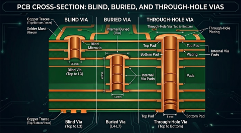
Microvia Geometry, Placement, and Intended Drill Strategy
Ultra HDI leans heavily on microvias for fanout from fine-pitch BGAs and in areas with dense routing. Their size, alignment, and stacking strategy are directly tied to reliability. When you reach the design review stage, make sure you’ve validated:
- Laser drill diameter and capture pad size based on the actual laser system your fabricator uses
- Aspect ratio each layer transition, specifically allowed aspect ratio for stacked microvias or skip microvias
- Sufficient offset for staggered microvias
- Whether any vias land too close to copper features that could shift during lamination
One example I’ve seen more than once: a perfectly reasonable set of stacked microvias on paper turns unreliable because the capture pad on layer 3 was drawn at a tolerance the fabricator has trouble meeting consistently. A small adjustment at design review, increasing a capture pad by a few microns or staggering a stack, can significantly improve long-term reliability.
Materials, Expansion, and Process Limits
This is the area where designers often underestimate Ultra HDI’s demands. In traditional HDI, you can absorb a bit of layer shift. In Ultra HDI, a tiny shift can wipe out a perfectly routed channel or undermine a microvia’s landing pad.
During your review, evaluate:
- The materials you’re calling out and their expected shrink/expand behavior
- Whether your stackup includes multiple build-up layers, and how their alignment impacts routing density
- Pad-to-feature spacing in regions where registration variability is most likely, under dense BGAs or at the transition from core to build-up
- Location-specific risks: inner layers may behave differently than outer buildup layers
Tip: If you’re working with very thin dielectrics, assume that the required registration margin is smaller than you think.
Copper Balance and Pattern Density Across the Stack
Copper balance matters in every PCB design, but in Ultra HDI it needs extra attention. Uneven copper distribution on thin materials and buildup dielectrics can distort lamination pressures, shift layers, and alter trace geometry. In your design review, look for:
- Large open areas next to dense routing fields
- Asymmetrical patterns between adjacent layers
- Regions where plating thickness could vary significantly because of pattern distribution
Your fabricator may address this with pattern thieving or other tooling adjustments, but it’s better when the design anticipates it.
Impedance Control with Realistic Tolerances
This conversation sometimes gets stuck in theory. Ultra HDI dielectric thicknesses are so thin that small shifts in copper geometry can move impedance noticeably. That isn’t a reason to fear UHDI, it’s simply a reminder to include impedance considerations in your design review.
Questions to consider:
- Are the stackup numbers based on real, production-verified values or datasheet nominals? Materials datasheets do not always distinguish.
- Are the calculations based on the actual copper weight used in build-up layers, or is there an assumption of 0.5 oz. or 1.0 oz.?
- Is your design too rigid to allow for the small changes in dielectric or copper parameters needed to hit target impedance within the allowed tolerance?
A quick impedance discussion now helps prevent a lot of back-and-forth after the first article is produced.
Solder Mask
As copper feature sizes shrink, designers tend to pack them closer together, so the solder mask requires extra attention. Some UHDI builds eliminate mask in specific regions to avoid registration, slivers, and opening-size issues. Others use advanced mask formulations with tighter control. Reducing the mask thickness may also be appropriate.
Your review should cover:
- Whether a mask will land cleanly between tight-pitch features
- If the technology requires a mask-defined (SMD) pad or a non-mask-defined (NSMD) approach
- Whether openings will remain stable with the shop’s imaging process
Mask doesn’t typically fail dramatically in UHDI, but it subtly contributes to yield reduction, particularly in assembly.
Data Package Completeness and Manufacturability
This may feel basic, but missing or unclear data can create unexpected problems in Ultra HDI builds where every detail matters. A complete design review includes a quick audit of the data package:
- Stackup and material callouts with thickness targets
- Via definitions with explicit diameters, tolerances, and drilling notes
- Fabrication notes that match UHDI-capable processes rather than default HDI language
- Clear identification of critical areas and keep-outs
And as always, if something is “implied” rather than documented, assume the shop will not guess correctly.
A Conversation with Your Fabricator
The best UHDI design reviews aren’t done in isolation. They include a conversation, sometimes as simple as a short call, with your fabrication partner. You learn what they’ve seen succeed in production, what trips up a first-time Ultra HDI design, and where to build in a little extra margin. In UHDI, execution depends on aligning design intent with manufacturing capability long before copper hits laminate.
UHDI rewards knowledge and discipline. When a design review looks past the surface checks and digs into registration, material behavior, microvia integrity, and true process limits, you end up with a board that builds cleaner, performs better, and avoids unnecessary surprises.
See what speed with structure looks like in practice. Start a free trial of Altium Agile Teams and explore how connected workflows, governed collaboration, and real-time visibility can transform the way your hardware team designs and delivers products.
Frequently Asked Questions
How is Ultra HDI different from traditional HDI, and why does it require a separate design review approach?
Ultra HDI isn’t just a smaller‑geometry version of HDI. It relies on different materials, copper‑forming processes (SAP/mSAP), tighter registration control, and much thinner dielectrics. These factors introduce new yield risks that do not show up in conventional HDI builds. A UHDI design review must therefore validate production capability (not just DRC clearance) by checking real trace/space limits, microvia aspect ratios, material movement, and pattern density.
What microvia issues most commonly cause failures in Ultra HDI designs?
The most frequent problems are related to stacking strategy, capture pad tolerance, and aspect ratio limits. Even small misalignments from lamination shift or undersized capture pads can compromise microvia integrity. Designers should confirm actual laser drill diameters, pad sizes, allowed stack heights, and stagger offsets based on the specific fabrication equipment to prevent reflow‑cycle or field‑life failures.
Why is material behavior so critical in Ultra HDI, and what should I verify during the stackup review?
Ultra HDI uses very thin dielectrics where even slight expansion, shrinkage, or glass‑weave movement can wipe out routing channels or shift microvia landings. During stackup review, validate the dielectric thickness tolerance, build‑up layer alignment behavior, and copper roughness, and make sure pad‑to‑feature spacing is sufficient in areas with high registration variability (such as under BGAs). Always use production‑verified material values, not datasheet nominals.
How do I ensure impedance and solder mask performance remain stable at Ultra HDI geometries?
For impedance, base calculations on the actual copper weight and dielectric thicknesses used in production, and allow some design flexibility for fine adjustments after first‑article builds. For solder mask, review whether slivers or registration limits make mask‑between‑pads risky. UHDI may require thin mask formulations, dry‑film solder mask, or even mask‑free regions to maintain yield and prevent assembly defects.
About Author
Related Resources
Related Technical Documentation
Table of Contents
- Key Takeaways
- Key Items For Every Ultra HDI Design Review
- Trace and Space at Production Tolerances, Not Nominal CAD Settings
- Microvia Geometry, Placement, and Intended Drill Strategy
- Materials, Expansion, and Process Limits
- Copper Balance and Pattern Density Across the Stack
- Impedance Control with Realistic Tolerances
- Solder Mask
- Data Package Completeness and Manufacturability
- A Conversation with Your Fabricator
- Frequently Asked Questions
- How is Ultra HDI different from traditional HDI, and why does it require a separate design review approach?
- What microvia issues most commonly cause failures in Ultra HDI designs?
- Why is material behavior so critical in Ultra HDI, and what should I verify during the stackup review?
- How do I ensure impedance and solder mask performance remain stable at Ultra HDI geometries?
Design to Release, Without the Friction
- Keep reviews tied to the right version
- Reduce handoff confusion and rework
- Spot sourcing and release risk earlier
- Work solo, share when needed
Get Started
Thank you, you are now subscribed to updates.