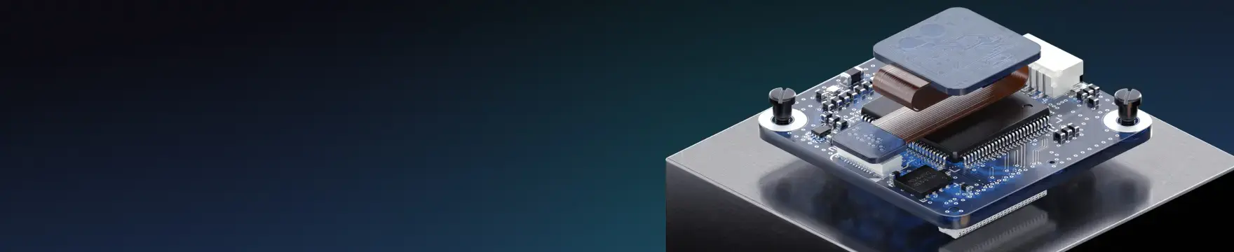


Registration Challenges in UHDI: Why Fabrication Tolerances Matter in Your Layout

At a Glance
Understand fabrication tolerances that shift UHDI layers by microns. Apply layout choices that prevent opens, shorts, and rework.


If you’ve ever taken a close look at first-article photos from an ultra-HDI build and spotted a via that feels a little too close to a nearby trace, or a pad that seems just slightly off-center, you’re in good company. It’s one of the most common questions designers ask when they step into the ultra-HDI world. In layout, everything behaves. Layers line up. Pads sit exactly where you put them. Nothing shifts unless you move it.
Once that design heads into fabrication, though, the real world shows up. Materials expand and contract. Films grow or shrink. Laser drills track fiducials that aren’t quite where they were a few hours earlier. These movements are tiny, often just a handful of microns, but in ultra-HDI, a handful of microns can be the difference between a clean interconnect and a reliability issue waiting to surface.
Let’s take a practical look at why registration is becoming such a defining challenge in UHDI and what designers can do early on to stay ahead of it.
Understanding Registration in the UHDI World
Registration is simply the art of getting every layer, via, and copper feature to land exactly where it’s intended. Designs with larger feature sizes have larger tolerance for misalignment between PCB layers, so a small amount of drift between layers will not be noticeable.
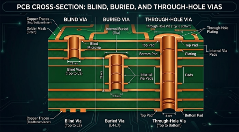
UHDI has much smaller features, with trace widths as low as 25 microns and tiny capture pads supporting laser-drilled microvias. When features shrink, the allowed tolerances also shrink. Misregistration that would go unnoticed on a standard HDI board could be larger than the copper feature sizes in a UHDI PCB, leading to a field failure if the board is released from production to a customer.
UHDI’s impressive capability only works when the design aligns with what the process can reliably deliver. When features don’t land where they’re supposed to, the consequences add up quickly:
- Microvias miss their capture pads, causing opens or intermittent failures.
- Soldermask shifts and exposes copper that should remain covered.
- Traces crowd into pad areas and trigger electrical test issues.
- Yield drops, cost rises, and build time stretches.
Why Registration Is Harder Than It Looks
Inside the factory, each fabrication step introduces a small amount of mechanically-driven or thermally-driven misalignment between PCB layers. This is expected and process engineers compensate where they can, but the feature misalignments still accumulate.
- Imaging: Photoresist responds to temperature and exposure energy, and even well-controlled imaging rooms experience humidity swings. Films can stretch slightly when they’re handled or scaled.
- Laser drilling: Laser drill heads are moved around a PCB with a CNC controller, and power delivery with a laser is highly precise. However, laser drills are not immune to mechanical hysteresis as they scan a PCB. They follow fiducials, and if those fiducials shift, even a little, so does everything else. A 10 to 15 micron drift across a thin UHDI panel is not unusual.
- Lamination: This is where the real balancing act happens. During each press cycle, resin flows, glass fabric moves, and every material reacts to heat differently. UHDI stack-ups often use very thin cores and multiple sequential lamination passes, which compounds the registration challenge.
A 10-micron shift on a standard multilayer PCB stackup barely registers. In UHDI, that same 10 microns can erase a soldermask dam or leave a microvia landing right on the edge of its pad. No amount of AOI or final inspection can put that tolerance back.
Where Designers Make the Biggest Impact
Fabricators invest heavily in reducing process variation, but the design itself often determines how tight the registration window must be. A few early choices can dramatically improve yield and stability.
- Build margin into your features: Yes, minimums exist, but they assume perfect alignment. Real boards rarely align perfectly. Give your design some breathing room wherever you can.
- Microvias: Stacked microvias demand extremely tight registration control. Staggered structures ease that requirement and often improve long-term reliability.
- Copper balance: Uneven copper distribution is a quiet troublemaker. Dense copper areas resist movement during lamination, while sparse areas shift more readily. The more uniform the copper weight, the more predictable the registration will be.
- Soldermask: Tiny apertures and narrow dams look crisp on the screen, but they leave almost no tolerance for mask shift. Even a small misalignment can close an opening or create unintended exposure.
Small decisions in the early layout stages often provide exactly the fabrication margin needed to keep everything in spec.
A Quick Look From the Fabricator’s Side
On the fabrication floor, registration control is a constant dance between precision tools and the physics of the materials. CAM teams use scaling models, alignment systems, and lots of historical data to predict how a panel will behave during processing. Those tools help, but they can’t override the innate movement of resin, glass, and copper during heat cycles.
That’s why early communication between design and fabrication is so important. When the fabricator understands your stack-up, your copper density goals, and your intended via architecture, they can tune their process window accordingly. Good registration isn’t a single adjustment, it’s the cumulative result of many small, coordinated decisions.
A little knowledge up front saves a lot of headaches later. You simply can’t inspect a misaligned feature back into tolerance. Designing for UHDI means designing with fabrication reality in view. Start with the stack-up discussion: the fabricator’s misregistration budget is a function of the specific materials being used in the UHDI stackup. Once the allowed tolerances are known, avoid unnecessary constraints that look elegant in CAD but tighten the fabrication window so much that the process becomes fragile.
Innovation is exciting, but execution wins the day. The designers who embrace this mindset tend to see smoother first-article runs, higher yields, and far fewer late-stage surprises.
Whether you need to build reliable power electronics or advanced digital systems, Altium Develop unites every discipline into one collaborative force. Free from silos. Free from limits. It’s where engineers, designers, and innovators work as one to co-create without constraints. Experience Altium Develop today!
About Author
Related Resources
Related Technical Documentation
Table of Contents
Design to Release, Without the Friction
- Keep reviews tied to the right version
- Reduce handoff confusion and rework
- Spot sourcing and release risk earlier
- Work solo, share when needed
Get Started
Thank you, you are now subscribed to updates.