Build an Electronic PCB Schematic Symbols Library in Altium Designer

Electronic symbols are the basis for the CAD documents you’ll create before you prepare a circuit board layout. An electronic symbols library contains basic symbols and figures that are used in electrical drawings, and they need to be linked to the PCB footprints that will appear in your PCB layout. When you need to prepare and organize clear PCB layouts and electrical drawings, you need a reliable source of CAD symbols and PCB footprints, and it helps to access these data in your PCB design application.
Altium Designer is the only program that gives designers CAD data for components and visibility in the electronics supply chain in the same application. Altium Designer makes managing electronic symbols library creation simple with a complete set of supply chain tools. Instead of cobbling together symbols from your old libraries or using a 3rd party service, use the industry’s best set of CAD tools for PCB design and electrical drawing creation.
ALTIUM DESIGNER®
The only application with industry-standard circuit board design tools and component management features in a single program.
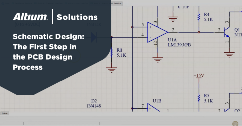
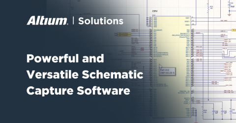
Designers of all experience levels have one thing in common: they all have to create circuit diagrams and electronics schematics when designing an electrical system. Circuit diagrams, electrical drawings, and electronics schematics all need symbols to represent various components, but designers don’t need to make their symbols from scratch. There are standardized symbols for many basic electronic components, but more complex components like large integrated circuits and connectors need very accurate and organized symbols.
Schematic symbols are important, but your components will need PCB footprints and 3D models if you want to create a real PCB from your schematics. When it’s time to start your circuit board layout, your components will need to include schematic symbols, PCB footprints, and 3D models in a single package that can be used in any PCB project. With the right design tools, you can easily create, manage, and place component models in any of your design documents.
Creating an Electronic Symbols Library
PCB CAD libraries are built by creating schematic symbols for components. When you want to include, for example, an operational amplifier, a symbol for the component needs to be created so that it can be used in your CAD drawings for your circuits. Although circuit drawings are a conceptual representation of a real circuit, a symbol needs to contain important information that relates back to a real component:
- Pin numbers and names: Pin numbers and names normally need to be included in a schematic symbol to indicate how the component should be wired.
- Manufacturer’s part number: Unless the part is a generic component, the MPN should be included in the schematic symbol as a comment.
- Reference designator: Every component needs a reference designator, which is normally placed in the upper-left corner of a circuit schematic symbol.
- Other notes: Some components need other notes to communicate important information to a designer. An example is a transformer, and it’s common to place the turns ratio in the design data as a note.
There are times where you will need to create your own schematic symbols, but the best design software can give you access to verified component data direct from manufacturers.
Where to Find Schematic Symbols for Your Libraries
You could spend time drawing out schematic symbols for every component in your design, but you can save yourself plenty of time when you use Altium Designer. The Manufacturer Part Search panel in Altium Designer allows users to search for components that include the CAD data they need for their schematics and PCB layout. This tool also provides supply chain information and sourcing data in the same window. You can quickly source the components you need for your design libraries when you use Altium Designer.
- Building libraries starts with creating a schematic symbol using CAD tools in your electrical design software.
Learn more about creating schematic symbols in Altium Designer.
- For more advanced components, like high pin count BGAs, Altium Designer helps you quickly create complex schematic symbols and add them to your electronic symbols library files.
Learn more about creating advanced schematic symbols in Altium Designer.
- The Manufacturer Part Search panel in Altium Designer helps you conduct web part lookups to find components that only have a complete package of CAD data for use in your design documents.
Learn more about using the Manufacturer Part Search panel in Altium Designer.

The Manufacturer Part Search panel in Altium Designer is the ideal tool to locate components with available schematic symbols for your electronic component libraries.
Your Circuit Board Layout Needs PCB Footprints
Real components for a circuit board need a PCB footprint and 3D model in addition to a schematic symbol. Each component needs to integrate all three pieces of information into a component library for use in PCB projects. Once you’re ready to create your PCB layout, your design tools will need to access data from your component part library so that you can create a real circuit board.
Just like symbols for electronic circuit diagrams, a designer may need to build their own PCB footprints for use in a circuit board layout. Some footprints are standardized and can be found in generic component libraries or manufacturer’s CAD data, but other components may need to be created from scratch. Just as is the case for symbol creation, Altium Designer makes footprint creation easy.
Watch this related video and checkout more PCB Design tips and guides on Altium Academy Youtube Channel
Altium Designer Helps You Build Your Component Libraries
PCB footprints can be much more complex than schematic symbols, but Altium Designer provides the features you need to create PCB footprints and assign them to components. You can build out your PCB libraries with the Manufacturer Part Search panel, and you can design your own footprints for specialty components. No matter how you want to build out your libraries, Altium Designer includes the tools you need.
- There are some simple steps you can take to build out complete component libraries with accurate CAD data, including symbols, PCB footprints, and 3D models.
- Altium Designer’s complete set of CAD tools makes the component creation process quick and easy. A design team can then place these new components in their PCB layout and reuse components in other projects.
Learn more about creating a PCB footprint in Altium Designer.
- IPC-compliant footprints have a specific set of formulas for creating components. The footprint generator in Altium Designer will create IPC-compliant footprints for use in your PCB projects.
Learn more about creating IPC-compliant component footprints in Altium Designer.

The Manufacturer Part Search panel in Altium Designer gives you a great estimate of prices and helps you find PCB footprints for your libraries.
Store and Manage Your Schematic Symbols in the Cloud
Instead of creating every schematic symbol from scratch, the right set of supply chain tools in a managed cloud-connected platform will give you access to the symbols you need. You don’t need to spend time recreating your electronic symbols library files in each new project, you just need to use the supply chain and component management tools available in Altium Designer.
The power of Altium Designer’s component library management features comes from its connection to Altium 365, the industry’s first complete platform for design data management. Altium 365 makes it easy to access components and design data from earlier projects and import components into new designs. You can also share your designs with other Altium Designer users, your customers, and manufacturers. No other cloud platform makes it so easy to access and manage component data in a single application.
Complete Design Management in Altium Designer and Altium 365
Altium 365 does more than just give you components you can use in Altium Designer projects. This unique cloud platform allows multiple designers to collaborate on their projects while providing version control, distributor part searches, user access management, design data sharing, and component library sharing. Best of all, these features are accessible within Altium Designer, giving design teams a complete design and data management solution.
- Altium Designer’s complete set of CAD tools create a unified PCB design experience. Component access, placement, and management are easy with Altium Designer’s industry-standard circuit board layout and management features.
Learn more about Altium Designer’s unified design environment.
- The Altium 365 platform gives Altium Designer users access to a complete solution for component access, sharing, and management. It’s easy to share and manage design within Altium Designer or in a web browser.
- When you want to bring Altium 365’s component data management capabilities on-premises, Altium Concord Pro provides an enterprise-level solution for component management that also integrates with Altium Designer.
Learn more about using Altium Concord Pro with Altium Designer.

You can share all your Altium Designer libraries and projects with the Altium 365 platform.
The days of sending emails with your project files and CAD libraries are over. Altium 365 makes sharing easy while keeping your design data secure, tracking revisions, and enabling complete project control within Altium Designer. No other design application provides this type of connected, collaborative PCB design experience.
Altium Designer on Altium 365 delivers unprecedented integration to the electronics industry until now relegated to the world of software development, allowing designers to work from home and reach unprecedented levels of efficiency.
We have only scratched the surface of what is possible to do with Altium Designer on Altium 365. You can check the product page for a more in-depth feature description or one of the On-Demand Webinars.


