


Stepped Impedance Transformer for Complex Loads

At a Glance
This article will show how a complex load can be converted to a real load with an impedance transformer for any line length and impedance.


There is a particular example of transmission line impedance matching that is sometimes sub-optimally discussed. I’m referring to the particular case of impedance transformer lines on a PCB with complex loads. In the case of a complex load, the typical quarter-wavelength impedance matching approach does not work, and we need a new approach.
In a previous article, I showed some of the important design points around quarter-wave impedance transformers. The most important conclusion about these designs is which loads are applicable when using a quarter-wave impedance transformer. To summarize:
- When the load is purely resistive: a quarter-wavelength impedance transformer can be used directly to match to the impedance of a transmission line on a PCB.
- When the load has reactance: the load impedance first needs to be transformed to a real impedance using another transmission line section before the quarter-wave impedance transformer. This forms a stepped impedance transformer.
This arises because transmission lines on PCBs are very nearly real; there is an imaginary component to their impedance, but it is small, even for the highest-loss materials. Thus, point #1 applies when the load is resistive or very nearly resistive (within 1%).
Point #2 is more general; when the load has reactance that is significant, matching to a transmission line at the input requires first transforming the load’s impedance so that its input impedance appears real. This article will provide an important identity that reveals how to solve this design problem using a transmission line with any impedance and length as the matching element.
How a Complex-to Real Stepped Impedance Transformer Works
Consider a complex that we need to match to a real input impedance. In this design, we only care that the input impedance is real, we don’t necessarily care what the specific impedance is. Once this complex load is transformed to a real input impedance, it could then be matched to any other real impedance using any other method; this would typically be done with a fractional wavelength transmission line, such as a quarter-wave impedance transformer.
The complex load, input transmission line, and unknown parameters of the impedance matching section are shown below.
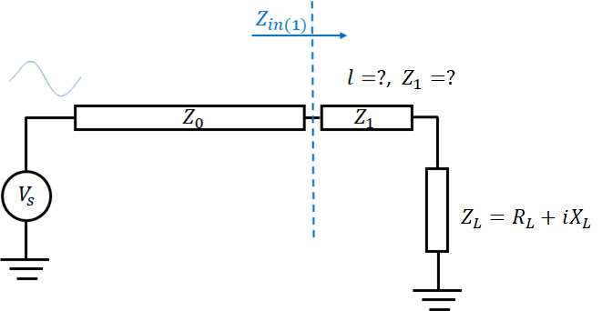
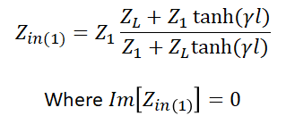
Here, Z0 is a transmission line with the system impedance, and Z1 is the transmission line used to match the complex load ZL. The input impedance at the interface between our two lines (at the blue dashed line) is shown below. We want to pick the length (l) and Z1 such that the input impedance is resistive.
A Universal Result With Real Input Impedance
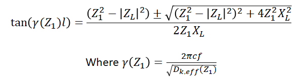
The design problem here is to ideally find the shortest length of transmission line that will give purely real input impedance. This allows us to approximate the line as lossless. In the lossless approximation with the complex load shown in the above circuit diagram, we have the following condition:
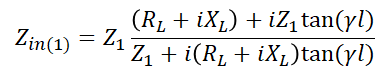
What follows is a simple manipulation with an important design consequence. If we multiply the numerator and denominator by the complex conjugate of the denominator, we can then break the input impedance equation into its real and imaginary parts. Once we do that, we can derive a condition relating the line length to the load impedance.
Eliminating the complex terms in the denominator and collecting like terms in the numerator above gives the following result:

Next, we take the imaginary part of the input impedance and set it equal to zero:

Here we have a quadratic equation in tan(γl). This gives us a simple result that relates tan(γl) to the load impedance and the matching transmission line’s impedance:
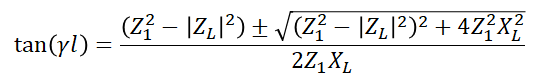
From this equation, we can pick any matching impedance Z1 given our load impedance ZL, and then this will determine the transmission line length:
- Pick your target impedance Z1
- Plug your chosen Z1 into the above equation to determine tan(γl) (you will get two values)
- Take the inverse tangent to get γl
- Use the result from #3 to get the line length as a wavelength fraction
This completes the design of the impedance transformer for any complex load impedance.
The Eighth-Wavelength Line Result
While reviewing a couple of guides on this topic recently, I realized that the examples presented in these guides always use a complex load with its magnitude of impedance equal to 50 Ohms! These designs always reduce to an eighth-wavelength transmission line, and this is proven in the result I show above.
If we have the case where Z1 = |ZL|, then the above solution to our quadratic equation reduces to tan(γl) = ±1. In other words, we can always set the matching line’s impedance equal to the magnitude of the load impedance. In this case, the line length will always be 1/8th of the signal wavelength:

The result here reduces to any odd multiple of 1/8th the signal’s wavelength. To stick closests to the lossless approximation, we pick n = 1 above to get the minimum line length of . This will always work for any load impedance as long as the load impedance has some reactance.
Sanity Check
As a sanity check, we can ask the following question: what happens if we set the imaginary part of the load impedance (XL) to zero? In this case, we can go back to the quadratic equation and insert XL = 0 into the equation. This gives the following result:
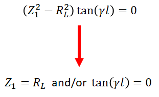
What does this result mean in terms of impedance matching? We have two options:
- We just matched two real impedances without requiring Z1 = Z0
- We have set the length of the matching line to 0
In both cases, the result is trivial and only needs a simple physical explanation to understand conceptually. In Case #1, the matching line has zero reflection coefficient at the load, so the matching section’s input impedance is exactly equal to RL regardless of line length. In Case #2, the matching line has zero length, so it is physically not present in the design. We are now back to the problem of matching the feedline’s impedance to a real load impedance.
A Note On Microstrips
If you look closely at the above result and you remember the definition of the propagation constant on a quasi-TEM microstrip transmission line, we actually have a 3rd parameter: the propagation constant. Remember, in microstrips, the propagation velocity is a function of the effective dielectric constant, which is then a function of the line’s width and thus the impedance Z1.
If you target a specific impedance matching microstrip line length first and try to determine the matching line’s impedance, you will need to solve a transcendental equation for the impedance of the matching line (Z1). This is because Z1 will appear as a variable inside the tangent function:
This will create a computational challenge because the above quadratic relation will only be solvable using intersections or series approximations. For this reason, in this design problem, we like to pick the line’s impedance first as this simplifies the computation. After you pick the line impedance, the impedance will entirely determine the propagation constant and you only have two design parameters to deal with in the above process.
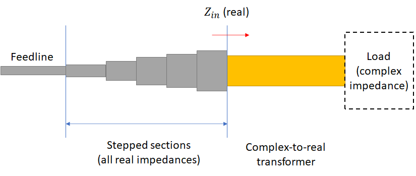
Approaching a Stepped Impedance Transformer
Just like the case of the quarter-wave transmission line, this all only works for a single wavelength, creating a high-Q bandpass filter that reflects at all other frequencies. If you want wideband matching, you need to cascade more lines to create a stepped transmission line, or you need to use a taper. If you’re trying to use these to match a complex load, both will require the transform to a real impedance be implemented as I’ve outlined above.
However, to increase the impedance matching bandwidth, one approach is to use stepped transmission line sections. The impedance matching section I’ve outlined here is the first step to building a stepped impedance transformer. With enough stepping sections, you can create a cascaded match between a real feedline impedance and a complex load impedance that has relatively flat bandwidth.
This is a much more difficult problem when looking at a complex load and with a complex-to-real matching section. Almost universally, what you will see in design guides is an assumption that the load impedance is not a function of frequency. This is a false assumption, and strong dispersion in the load impedance may preclude the use of a complex-to-real impedance transformer.
The superior approach is to just use a taper. This is a superior approach because it is much easier to design and place in a PCB. I have never seen a stepped line used in practice, but that is not to say you cannot use one. I’ll discuss RF tapers more in an upcoming article.
Summary
In reality, any transmission line with length and impedance solving the quadratic equation shown above will produce a purely real input impedance for any load with complex impedance. It’s a good idea to pick a load impedance that you can actually fit on the PCB. For example, if you take the eighth-wavelength approach and the matching transmission line section is very low impedance, this will require a very wide line in your design (assuming microstrips), or it could require very low clearance in coplanar routing that might violate trace-to-copper clearances.
If this line is not practical to implement, then you can pick a higher impedance line (it will have smaller width) and calculate the line length you need for impedance matching. This is one reason you might see the following configuration for use of a quarter-wave impedance matching transformer with a complex load: the matching section and feedline are sometimes set to the same impedance since that reduces the number of required impedances from 3 to 2.
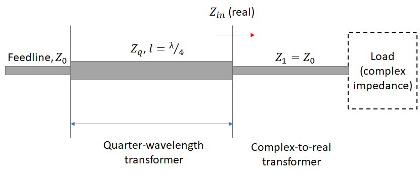
The widths indicated in the figure are just a sketch, but they are meant to indicate the typical magnitude you might see in these results with practical impedances in RF systems. Don’t be afraid to try this strategy and the eighth-wavelength strategy, and then compare these to see which will work best in your system.
When you need to design and route transmission line sections in your RF design, use the complete set of PCB design tools in Altium Designer®. When you’ve finished your design, and you want to release files to your manufacturer, the Altium 365™ platform makes it easy to collaborate and share your projects.
We have only scratched the surface of what’s possible with Altium Designer on Altium 365. Start your free trial of Altium Designer + Altium 365 today.

About Author
Related Resources
Related Technical Documentation
Table of Contents
Design to Release, Without the Friction
- Keep reviews tied to the right version
- Reduce handoff confusion and rework
- Spot sourcing and release risk earlier
- Work solo, share when needed
Get Started
Thank you, you are now subscribed to updates.

