


From Mechanical Drilling to Laser Drilling of PCB Microvias

At a Glance
Miniaturization of PCB designs eventually forces a switch from mechanical drilling to laser drilling. Learn more about sizing vias for your next multilayer PCB.


PCB via fabrication relies on a specialized process of drilling and plating, where the drilling step is executed in two possible ways: mechanical drilling and laser drilling. Mechanical drilling is the practice used for standard PCBs where the hole sizes are not too small. HDI (High-Density Interconnect) design practices can be used for mechanical drilling, but only down to a certain limit. Eventually, laser drilling will be needed to fabricate a PCB, which is determined by the diameter of the holes that need to be drilled and the thickness of the layer where holes are being placed.
It is the designer's responsibility to understand the limits of mechanical drilling and laser drilling. If laser drill hole sizes are specified in a laminate thickness or material type that cannot be laser drilled, you will be forced to make changes to the PCB design in order to proceed to production.
If you want to avoid the need to make changes to your design before manufacturing, pay attention to the mechanical drilling and laser drilling limits defined in this article.
PCB Drilling Limits
As drilled holes get smaller in a PCB, they run up against certain fabrication limits, which should be considered in the design. In general, drill size limits will be selected based on the following factors:
- Total board thickness for through-hole vias
- Layer or lamination thickness for blind/buried vias
- Fabrication process being used
- Desired landing pad size and annular ring requirement
- Manufacturer's capability limits
Keep these points in mind as we look at the typical size restrictions on drills.
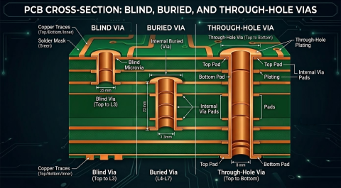
Through-Hole Mechanical Drilling Limits
Mechanical drilling is primarily limited by available drill sizes; you can only drill so small before you have to switch to laser drilling. The mechanically drilled hole diameter and the board thickness define an aspect ratio limit for a particular drill size. Your aspect ratio needs to stay below a certain value for a given hole diameter, and this will limit the total board thickness.
What are the exact aspect ratio limits? This depends on the limits set by your fabrication house. They can only guarantee accurate hole size and positional tolerance for certain maximum aspect ratio values. An example for a few drill diameters is shown in the following table.
|
Aspect ratio |
Typical values:
|
|
Drilled hole diameter |
6 mil minimum |
|
Positional tolerance |
Based on IPC Producibility Level |
|
Pad size |
Based on IPC annular ring/product class |
Table 1: Typical mechanical drilling limits for vias
Different PCB fabrication houses may have different aspect ratio limits, so check with them before creating your design. If you do not check with them first, you risk being given holes that are too small, and once the design is corrected with a larger hole, there may be clearance problems that need to be resolved.
Laser Drilled Microvia Limits
Laser drilling allows for very fast throughput during manufacturing, but it has limited drilling depth into the PCB material. Due to the limitation on drilling depth, the aspect ratio limitation on laser-drilled microvias will be much lower. Typical values you might find in a standard microvia laser drilling process are shown in the following table.
|
Aspect ratio |
Typical values:
|
|
Drilled hole diameter |
2-3 mil minimum |
|
Positional tolerance |
Based on IPC Producibility Level |
|
Pad size |
Based on IPC annular ring/product class |
Table 2: Typical laser drilling limits for microvias
Laser-drilled microvias with an aspect ratio less than one generally require very thin dielectric layers. However, larger microvias can also be fabricated, though they won’t really be classified as microvias despite the fact that they are laser-drilled. For example, the 10 mil maximum laser drill hole diameter limit with a 0.75:1 aspect ratio demands a laminate thickness of 7.5 mils. Typically, if you intend to place drills with this diameter as blind or buried vias, you would use mechanical drilling, which I detail more in the next section.
An important point regarding the fabrication of laser-drilled microvias is that the pre-preg material being used must be laser-drillable. Not all PCB laminate materials are marketed as laser-drillable, although the growth in HDI markets has greatly expanded the range of compatible materials.
When viewed under the microscope, laser-drillable materials that can be used as HDI buildup layers in sequential lamination are not much different from standard materials in terms of structure. You still have the same glass weave styles and similar resin material systems.

The materials shown above are standard FR4-grade laminates, but many other materials are available for use in these designs as HDI buildup layers. To learn more, read this excellent article about HDI materials by Happy Holden.
Mechanically Drilled Blind and Buried Vias
Blind and buried vias can also be mechanically drilled. For example, consider Type 2 and Type 3 HDI stackups: these use a buried via in the central core, and the HDI buildup layers are placed around the core using sequential lamination. The central core via typically has to pass through a thicker core layer stack, thus the aspect ratio will demand mechanical drilling. Examples of these two types of HDI stackups are shown below.

What are the drilling limits in this case? Typically, because this is placed as a mechanically drilled via, it will first obey the drill bit sizing limit, which means the smallest drilled hole size would be 6 mils. Next, there may be an aspect ratio limit that must be obeyed based on your manufacturer's capabilities, just as I outlined above. This should also be investigated if you are considering a Type 2 or Type 3 HDI stackup.
Don't Forget About the Stackup Materials
The rules discussed here apply to HDI PCB stackups, which drive layer thickness limits in the design. These stackups will experience reliability challenges related to thermal excursions, which lead to failure of plating at microvia interfaces, especially when microvias are stacked. While microvias can be fabricated in high-Dk FR4 materials, the high CTE values of these materials (70 ppm/C in the z-axis) limits the number of allowed build-up layers and the number of microvias that can be stacked.
This is where materials play a key role in ensuring reliability and will constrain the allowed number stacked microvias as well as the total number of HDI build-up layers. THe HDI material options readily available today are listed in this article by Happy Holden. These materials have some common properties:
- Low thickness (3 mil or less) for low aspect ratio microvia fabrication
- Laser-drillable
- CTE value (z-axis) closer to the value for bulk copper (~17 ppm/C)
- Compatible with advanced metallization processes
For example, consider the common substrate construction with BT epoxy for the core and ABF for the HDI build-up layers containing microvias. While this is common in IC substrates, it is useful for HDI designs as the materials are readily available.

We also have ELIC stackups, which are the PCB version of a coreless substrate. In this construction, all of the layers in the HDI stackup are build-up film layers with microvias. These could be stacked through the entire stackup as long as the fabrication house allows. Some fabrication houses have very god qualification, quality control, and analysis practices for ELIC designs when standard build-up film materials are used. The result is am HDI PCB that looks similar to the coreless package shown in the image below.

When planning out the use of microvias for fanout routing from fine-pitch BGAs, count up the number of HDI routing layers first to determine the appropriate stackup type. Most fine-pitch components can be fanned out using an i+N+i HDI stackup that looks like the 4+2+4 ABF/BT epoxy package shown above. Before finalizing the stackup, determine whether your fabrication vendor can support your required number of build-up layers and determine the DFM constraints for the HDI stackup.
Whether you need to build reliable power electronics or advanced digital systems, use the complete set of PCB design features and world-class CAD tools in Altium®. Only Altium provides the world’s premier electronic product development platform, complete with the industry’s best PCB design tools and cross-disciplinary collaboration features for advanced design teams. Contact an expert at Altium today!

About Author
Related Resources
Related Technical Documentation
Table of Contents
Design to Release, Without the Friction
- Keep reviews tied to the right version
- Reduce handoff confusion and rework
- Spot sourcing and release risk earlier
- Work solo, share when needed
Get Started
Thank you, you are now subscribed to updates.


